4-585-174-04 (1) Digital Wireless Microphone Operating Instructions DWM-02N © 2015 Sony Corporation
Table of Contents Features ...................................................................... 3 Parts Identification ................................................... 4 Power Supply ............................................................. 5 Installing the Batteries ........................................... 5 Attaching the Supplied Accessories ......................... 6 Replacing the Identification Ring .......................... 6 Setting the Transmission Channel ...........................
Interchangeable microphone capsule Features Coupled with a Sony microphone capsule unit (not supplied), the DWM-02N can be used in vocal performances, interviews, speeches, and a variety of other applications. You can mount a microphone capsule unit by simply screwing it onto the capsule mounting area at the top of the DWM-02N. The capsule mounting area has standard dimensions with a diameter of 31.3 mm and a pitch of 1.0 mm (1.25"/28 thread pitch).
d Antenna cover Holds the antenna for RF transmission and wireless remote control function. Parts Identification e POWER indicator Lights up green when the microphone is turned on. When the battery is exhausted, the indicator starts flashing. f USB connector (Micro USB) Use this connector to connect an optional USB keyboard to carry out menu functions using key operations.
F POWER switch lock indicator Indicates that the POWER switch is locked, preventing the microphone from being accidentally turned off or on. Power Supply For details, see “Locking the POWER Switch (POWER SW LOCK)” on page 14. The microphone can operate on two LR6 (size AA) alkaline batteries continuously for about 5 hours at 25 °C (77 °F). G Cross Remote condition indication Indicates the signal transmission condition of the wireless remote control function (4 levels).
• If you plan to use the microphone for a long period of time, it is recommended that you replace the batteries with brand new ones. Attaching the Supplied Accessories For details on BATTERY TYPE setting, see “Setting the Battery Type (BATTERY TYPE)” on page 13. Replacing the Identification Ring A black ring is attached at the factory. When multiple microphones are used in the system, identification rings with different colors are useful to distinguish a microphone from another.
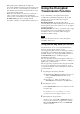
Setting the Transmission Channel The microphone provides groups of interference-free channels. When using multiple microphones and transmitters at the same time (simultaneous multi-channel operations) within the same area, selecting the same group and using a channel within that group can prevent signal interference. To set the transmission channel on the microphone, first you select the group and channel using the RF indicator and scanning functions on the receiver.
When pairing has been established, the wireless remote control condition level (indicated by ) goes up, RF REMOTE turns on, and the remote control function becomes operative. Using the Cross Remote This microphone is equipped with a wireless remote control function that can be used to set the parameters (low-cut filter, attenuation operation, power save mode, etc.) of the microphone through the receiver or other devices.
• When pairing fails (“Pairing fail” is displayed), successful communication between the microphone and the receiver has not occurred within a given amount of time. Pairing may be harder to do when another receiver is engaged in pairing nearby. • When it becomes hard to use the remote control, the remote control may be improved by switching the wireless remote control function off, then on again in the RF REMOTE display, then re-pairing with the microphone (change to a channel with less interference).
5 Note When the receiver does not support encryption key exchange through USB connection, select REMOTE. For details on receiver operations, refer to the operating instructions supplied with the receiver. For details on the receiver, refer to the operating instructions supplied with the receiver. Note It is recommended that you change the password periodically. When you select USB: Connect the microphone to the receiver using a USB cable (not supplied) and the USB adapter cable (supplied).
Using a USB Keyboard Basic Menu Operations Connecting an optional USB keyboard to the microphone allows you to perform menu operations and enter your name and password for the encrypted transmission function from the keyboard. A Micro USB connector is used on the microphone. For this reason, use the supplied USB adapter cable.
off the microphone first. Then, while holding down the SET button, turn the power on. Then change the setting after the signal transmission has stopped. • Be sure to select the group/channel right after selecting the frequency band. To start signal transmission with the selected frequency band/group/channel, turn off the power and then turn it on again. Setting Menus The functions and parameters of the settings menu are explained here. Underlined items are the factory setting.
Input MIC Attenuation Reference Maximum (dB) input level input level (dBu) (dBu) Headroom (dB) 0 –52 –16 36 3 –49 –13 6 –46 –10 9 –43 –7 3 dB steps 3 dB steps 3 dB steps 45 –7 +29 48 –4 +32 Setting the Battery Type (BATTERY TYPE) Set this item according to the type of batteries you use to obtain accurate battery power status indication. TYPE1: The power status is indicated based on characteristics of new LR6 (size AA) Sony Alkaline batteries.
the receiver or the system that you are using. This internal signal is outside the control of the attenuator. Setting the audio codec mode (CODEC MODE) 1kHz: A 1-kHz internal signal is generated. OFF: An internal signal is not generated. MODE1: This audio codec mode is compatible with the first generation DWX series. MODE2: Delay times are reduced in this audio codec mode. Audio quality is also improved when compared to MODE1. We recommend using this mode under normal circumstances.
Setting the Brightness of the Display (BRIGHTNESS) Ten levels of brightness can be selected for the organic light-emitting diode display. The selectable settings are the following: (Dark) 1 2 3 4 5 6 7 8 9 10 (Bright) Automatic Dimming of the Display (DIMMER MODE) The organic light-emitting diode display can be set to dim or turn off after a certain amount of time. AUTO OFF: The display turns off after 30 seconds. The display goes on again when you press the SET, +, or – button.
Block Diagram Microphone capsule Attenuator Digital signal processor Head amp.
Troubleshooting If you encounter a problem using this microphone, use the following checklist to find a solution. For any problems with the receiver, refer to the operating instructions supplied with the receiver. If the problem persists, consult your Sony dealer. Symptom Meanings Remedy The microphone does not turn on. The batteries are inserted backwards in the battery compartment. Reinsert the batteries with the correct orientation (see page 5). The batteries are exhausted.
antenna of a receiver for up to 10 channels, and at least 6 m (20 feet) away for 11 or more channels. • When a mixture of digital and analog wireless microphones/transmitters is being used, keep the microphone at least 6 m (20 feet) away from the antenna of a receiver. • This system should be kept at least 100 m (328 feet) away from any analog wireless systems using the same frequency when both are being used in a wide area with no walls or obstructions.
Dimensions (unit: mm (inches)) Specifications ø37.1 (1 1/2) Transmitting section Oscillator type Crystal-controlled PLL synthesizer RF power output 1 mW/10 mW/50 mW (e.r.p) selectable Antenna type Helical antenna Occupied RF bandwidth 192 kHz or less Audio delay MODE1: 1.5 ms MODE2: 1.0 ms MODE3: 2.1 ms Allowable deviation of transmission frequency ±6.5 ppm Type of emission G1E or G1D Modulation method π/4 Shift QPSK 194 (7 3/4) Mass approx. 235 g (8.
Carrier Frequencies and Channel Steps Underlined items are the factory setting. Channel step: 25 kHz Model No. 14UC (TV14-25) 30UC (TV30-41) 30A UC (TV30-36) 42LA (TV42-51) 21CE (TV21-29) 33CE (TV33-40) 42CE (TV42-50) Frequency band Frequency TV14-17 470.125 - 493.875 MHz TV18-21 494.125 - 517.875 MHz TV22-25 518.125 - 541.875 MHz TV30-33 566.125 - 589.875 MHz TV34-36 590.125 - 607.875 MHz TV37 Not available TV38-41 614.125 - 637.875 MHz TV30-33 566.125 - 589.875 MHz TV34-36 590.
Sony Corporation