5-014-891-01 (1) Digital Wireless Transmitter Operating Instructions DWT-B30 © 2019 Sony Corporation
Notes on simultaneous multi-channel operation ............................................................ 18 Note on microphone and transmitter combinations ...................................................... 18 CROSS REMOTE Compatibility ........................ 18 Specifications ........................................................... 19 Carrier Frequencies and Channel Steps ............... 20 Table of Contents Features ......................................................................
Encrypted transmissions Features AES 256-bit encryption allows for highly secure wireless transmissions. The DWT-B30 is a digital wireless transmitter for a UHF synthesized wireless microphone system to be used for broadcast or movie production purpose. This transmitter is suitable for Electronic News Gathering (ENG) and Electronic Field Production (EFP).
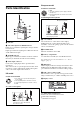
European model Parts Identification Connector front view 1: GND 2: +5.2 V DC output (for power supply of lavalier microphone) 3: HOT (input impedance 4.7 kohms or more with +5.2 V DC) Connecting the microphone Microphone (optional) To secure the connection, turn the ring on the connection plug to lock it. e + or – button Selects functions or values shown on the display. Holding down the – button while switching on the transmitter activates the pairing operation for the wireless remote control function.
B RF (radio frequency) transmission power indication Indicates the current transmission power setting. You can change the setting with the RF transmission power setting function. H: transmitting at 25 mW M: transmitting at 10 mW L: transmitting at 2 mW Power Supply The transmitter can operate on two LR6 (size AA) alkaline batteries continuously for about 6.5 hours at 25 °C (77 °F). Connecting a mobile battery to the USB connector enables operation for a long period of time.
• Operation is not guaranteed on all USB power sources. Make sure to test the power source before using it. • The transmitter cannot be used when connected to a USB device that possesses communication functions, such as a computer. Setting the Transmission Channel For details on BATTERY TYPE setting, see “Setting the battery type (BATTERY TYPE)” (page 11). The transmitter provides groups of interference-free channels.
2 3 Press the + or – button repeatedly until the GP/CH indication is displayed. Using Cross Remote Hold down the SET button until the item to be set flashes. 4 Press the + or – button repeatedly to select a group. 5 Press the SET button to enter the group. This transmitter is equipped with a wireless remote control function that can be used to set the parameters (low-cut filter, attenuation operation, power save mode, etc.) of the transmitter through the receiver or other devices.
goes up, RF REMOTE turns on, and the remote control function becomes operative. Using the Encrypted Transmission Function To use the Cross Remote with a previous pairing In the RF REMOTE indication, select ON. The unit is capable of transmitting encrypted signals to prevent unwanted surveillance. To use the function, select one of the following encryption modes.
3 Exchange the encryption key. Basic Menu Operations On the receiver side, select REMOTE (wireless remote) as the encryption key exchange method, and perform encryption key exchange. REMOTE cannot be selected when the wireless remote control function is disabled. Function name Note If the receiver does not support AES256 mode, select SECURE KEY. Item to be set For details, refer to the receiver’s operating instructions. 1 The unit searches for the receiver with which it is paired.
selected frequency band/group/channel, turn off the power and then turn it on again. Setting Menus Selecting the group/channel (GP/CH) The functions and parameters of the settings menu are explained here. Underlined items are the factory setting. See “Carrier Frequencies and Channel Steps” (page 20) for factory settings. Unit name setting (NAME) For details, see “Selecting the group/channel” (page 6). You can specify a transmitter name of up to 16 characters.
For details on wireless remote control function, see “Using Cross Remote” (page 7). You can also use the wireless remote control to change the receiver back to normal operation. Lock function (LOCK) For details on wireless remote control function, see “Using Cross Remote” (page 7). Lock and prevent operations such as those for the POWER button and for settings changes. This prevents you from accidentally turning the unit off, for example.
For details, see “Using Cross Remote” (page 7). Audio codec mode setting (CODEC MODE) Audio phase switch function (AF PHASE) MODE1: Audio codec mode that is compatible with first generation DWX-series devices. MODE2: Audio codec mode that prioritizes short delay times while maintaining transmission stability and high audio quality. MODE3: Audio codec mode that uses additional signal processing to suppress noise caused by unexpected pulse interference.
For details, see “Setting the maximum RF output power (MAX RF POWER)” (page 13). Automatic dimming of the display (DIMMER MODE) Setting the maximum RF output power (MAX RF POWER) The organic light-emitting diode display can be set to dim or turn off after a certain amount of time. You can set the maximum RF output power of the unit. AUTO OFF: The display turns off after 30 seconds. The display goes on again when you press the SET, +, or – button. AUTO DIMMER: The display dims after 30 seconds.
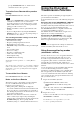
- Pairing the unit or establishing encrypted transmission with a different receiver. - Pairing the receiver that was paired with the unit with a different transmitter. - Establishing encrypted transmission between the receiver and a different transmitter. Attaching With the Soft Case The transmitter can be attached to the user with the supplied soft case.
Rear Fig. 2 Hook and loop fastener Belt Hook and loop fastener Front Removing the unit from a belt When the soft case is attached to a belt with the unit’s antenna pointing up, be careful to avoid getting the soft case’s hook and loop fastener caught on the belt during removal. The hook and loop fastener may open if it gets caught on the belt. To avoid contact between the fastener and belt, tilt the bottom of the soft case outward (Fig. 1) or rotate the case to the left or right (Fig.
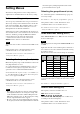
Block Diagram US model Attenuator 1: +5.2 V (output) 2: HOT 3: COLD 4: GND Digital signal processor Head amp. Low-cut filter Audio codec modulator A/D converter Highfrequency circuit Internal SG European model Attenuator 1: GND 2: +5.2 V (output) 3: HOT +5.2 V Head amp.
Troubleshooting If you encounter a problem using this transmitter, use the following checklist to find a solution. For any problems with the receiver or adapter, refer to the operating instructions supplied with the respective device. If the problem persists, consult your Sony dealer. Symptom Meanings Remedy The transmitter does not The batteries are inserted backwards in the turn on. battery compartment. Reinsert the batteries with the correct orientation (see page 5). The batteries are exhausted.
the antenna of a receiver for up to 10 channels, and at least 6 meters (20 feet) away for 11 or more channels. • When a mixture of digital and analog wireless microphones is being used, keep the transmitter at least 6 meters (20 feet) away from the antenna of a receiver. • This system should be kept at least 100 meters (328 feet) away from any analog wireless systems using the same frequency when both are being used in a wide area with no walls or obstructions.
Operating temperature 0 °C to 50 °C (32 °F to 122 °F) Specifications Note When used in locations with an ambient temperature of 45 °C (113 °F) or higher, make sure the unit does not come into direct contact with your skin, as it may cause burns due to high temperature. Storage temperature –20 °C to +60 °C (–4 °F to +140 °F) Wireless remote control 2.4-GHz IEEE802.15.
Carrier Frequencies and Channel Steps Underlined values represent factory settings. US model Channel step: 25 kHz Frequency band Frequency Group/channel (factory setting) TV14-17 470.125 - 493.875 MHz 00 1801 494.125 MHz TV18-21 494.125 - 517.875 MHz TV22-25 518.125 - 541.875 MHz TV26-29 542.125 - 565.875 MHz TV30-33 566.125 - 589.875 MHz TV34-36 590.125 - 607.875 MHz TV37 Not available TV38 614.125 - 615.875 MHz The maximum transmission power (MAX RF POWER) for TV38 (614.125 - 615.
Sony Corporation