
User's Manual


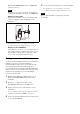
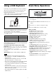
Table Of Contents
- Table of Contents
- Features
- Parts Identification
- Power Supply
- Setting the Transmission Channel
- Using the Cross Remote
- Using the Encrypted Transmission Function
- Using a USB Keyboard
- Basic Menu Operations
- Setting Menus
- Block Diagram
- Troubleshooting
- Important Notes on Operation
- Specifications
- Carrier Frequencies and Channel Steps

5
D Reference level gauge
Indicates the reference input level. When the attenuation is
0 dB with INPUT LEVEL set to MIC, –58 dBu (–60 dBV)
is indicated. When LINE is selected for INPUT LEVEL,
+4 dBu is indicated.
E Peak indicator
Warns of excessive input by lighting up when the signal is
3 dB below the level at which distortion begins.
F POWER switch lock indicator
Indicates that the POWER switch is locked, preventing the
transmitter from being accidentally turned off or on.
For details, see “Locking the POWER switch (POWER SW
LOCK)” on page 14.
G Cross Remote condition indication
Indicates the signal transmission condition of the wireless
remote control function (4 levels).
: Good transmission
: Somewhat good transmission
: Somewhat poor transmission
: Poor transmission
: Unable to communicate with paired receiver
When the wireless remote control function is off, this
indication does not appear.
H Battery indication
Shows the battery condition.
For details, see “Battery indication” on page 6.
I Menu display section
The status of 20 different functions are displayed here. To
select the function, press the + or – button repeatedly.
For details, see “Setting Menus” on page 11
f + or – button
Selects functions or values shown on the display.
Holding down the – button while switching on the
transmitter activates the pairing operation for the wireless
remote control function.
g SET button
Adjusts displayed function settings and enters the value.
Holding down the SET button while switching on the
power turns the transmitter on without sending a signal.
h USB connector (Micro USB)
Use this connector to connect an optional USB keyboard to
carry out menu functions using key operations. By
connecting the digital wireless receiver to this connector
using a USB cable (not supplied) and the USB adapter
cable (supplied), you can exchange the encryption key for
encrypted transmission function.
i POWER switch
Turns the transmitter ON or OFF.
j Battery compartment
Accommodates two LR6 (size AA) alkaline batteries.
For details on how to insert the batteries, see “Power
Supply” on page 6.