3-204-941-14(1) Video Network Station User’s Guide GB Page 2 Guide de l’utilisateur SNT-V304 2000 Sony Corporation Page 52 FR
English WARNING To prevent fire or shock hazard, do not expose the unit to rain or moisture. To avoid electrical chock, do not open the cabinet. Refer servicing to qualified personnel only. For the customers in the USA This equipment has been tested and found to comply with the limits for a Class B digital device, pursuant to Part 15 of the FCC Rules. These limits are designed to provide reasonable protection against harmful interference in a residential installation.
Table of Contents Video Network Station Features ...................................... 4 Part Names and Functions ............................................... 5 Front Panel ..............................................................................5 Rear Panel ...............................................................................6 System Application Examples ......................................... 7 Installation ..........................................................................
Video network station Features Video Network Station Features This unit is a video network station that distributes real-time CCTV images over a LAN or the Internet. Simple monitoring over a network • By assigning an IP address to this unit, live video can be monitored using standard Web browsers on client PCs. • The unit can be set up and controlled from a Web page.
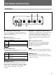
Part Names and Functions Front Panel 6 S VIDEO POWER STATUS NETWORK VIDEO 1 VIDEO 2 7 VIDEO 3 VIDEO 4 75Ω OFF 1234 75Ω ON 1 2 34 5 1 S VIDEO Input Terminal (4 pins) Video sources that provide separate Y/C signals are input here. The VIDEO 1 input terminal is not usable when this terminal is used. 2 STATUS Indicator Indicates the operating status of the unit. Color Server Status Orange The self-test is executing after turning power on. (blinking) Green Normal operation Red Fault.
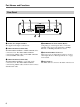
Part Names and Functions Rear Panel 1 2 ~ ~ 1 AC IN (12V) 2 A3 C3 A4 C4 B 3 4 5 6 7 COM 2 ETHERNET 10 /100 – A1 C1 A2 C2 RELAY 6 1 AC IN (12 V) Input Terminal The supplied AC adapter connects here. 2 COM 1 Terminal (9-Pin D-Sub) The EVI-D30/D31/G20/G21 or HSR-1/1P/2/2P can be connected to here. The EVI-D30/D31/G20/G21 connects using VISCA cable, and the HSR-1/1P/2/2P connects with RS-232C cable. 3 COM 2 Terminal (9-Pin D-Sub) The EVI-D30/D31/G20/G21 or a modem can be connected to here.
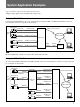
System Application Examples • Up to four video sources can be connected to the server. • Highest image quality can be distributed by using S-video. Using the EVI-D30/D31 Connecting an EVI-D30/D31 to the video network station using the COM1 or COM2 terminal allows control of pan, tilt and zoom from a computer on the network.
Installation Installation After connecting the video sources and the network to the video network station, turn on the power switch and set the IP address. About the Operating Environment The following operating environment is required to set up the server and view the images. • Computer: 400-MHz Pentium III with 64-MB RAM or more • Operating System: Windows 98, Windows Me, Windows NT 4.0 SP5 or later, or Windows 2000 • Web browser: Internet Explorer 5.0, 5.
Assigning the IP Address 1 Enter the following commands at an MS-DOS prompt (or command prompt) on a computer on the network: arp -s
Installation Accessing the Video Network Station 1 2 Run the Web browser. Enter the following in the [Address] box, and press the Enter key: http:/// The “Welcome” page appears. Note Response may be slow depending on the condition of the network. If screen display is delayed, stop the URL loading, and try accessing again.
Settings This chapter describes how to set up the video network station for various system types and applications. Video network station settings are made using Internet Explorer 5.0 or 5.5. The Wizard appears. Note If the computer used for making video network station settings or viewing the monitor screen is shared with other users, we recommend closing the Web browser when finished operations.
Settings Accessing the Administration Overview Page Click the (Admin) button to display the “Administration overview” page. After basic settings have been made with the “First Time Installation Wizard”, all video network station settings and management are performed from the “Administration overview” page. 1 Launch the Web browser and enter the following in the [Address] box, and press Enter. http:/// The monitor screen appears.
Monitor Screen and Alarm Function Setup The (Application Design) icon is used to configure the monitor screen display and to determine the operation of the video network station when an alarm event occurs. Clicking the “Application Design” icon displays the following screen.
Settings Alarm Settings Setting Description Alarm Buffer, Overwrite A pre-determined amount of memory is used to store images before and after an alarm event. If the quantity of images exceeds the allotted amount, select whether to overwrite previously stored contents, oldest first. Select either [ON] (overwrite) or [OFF] (no overwrite). Alarm Pop-Up Window Select whether a pop-up window should appear when an alarm event occurs: either [Enable] (display popup) or [Disable] (no pop-up).
• When an alarm event occurs while the pop-up window is displayed, the time set for the [Alarm duration] is extended. A second pop-up window will not appear. Setting Description Overwrite To always overwrite the same file name, select this radio button. Date/Time Suffix Select this radio button to append the date and time to the base file name. Upload Settings Sequence Number Select this radio button to append a Suffix set to sequential number to the prefix.
Settings Settings can be made with the following procedures. • (Network Wizard) icon: click to display Wizard instructions for making the settings. • (Detailed View) icon: click to display a dialog box with [TCP/IP], [DNS] and [SMTP EMail] tabs that you can select to make corresponding settings. Settable contents are shown in the following table. Setting Description TCP/ BOOTP* IP Enable the BOOTP protocol to automatically download the IP address.
The setting items are shown in the following table. When finished setting, click the “Save” Icon. The accuracy of the internal clock is ±120 seconds/month or less. Setting Description Date & Time Format Select the display format for date and time on the monitor screen from the drop-down list. 12h/24h Current Camera Time Select either [12h] or [24h] for 12- or 24-hour time display. Displays the current date and time. The displayed date and time cannot be edited.
Settings 3 4 Click the “Add” icon. Displaying the Log File Repeat the above steps to add more users. Up to 20 users can be registered. 5 Click the [Close] button to close the dialog box. Clicking the (View Log File) button opens a new window to display the “Log file Events” page. Recently executed commands are displayed on the “Log file Events” page. The log file is used to check whether a special event was executed, such as whether a command was issued before or after an alarm occurred.
Serial Port Settings Setting Options Description Purpose Modem (only displayed for COM2) Select this if a modem is connected to the port. When selected, the “Modem” and “ISP” icons shown below are displayed. Generic Select if using a CGI/Generic driver. When selected, the following “Generic” icon is added next to the [COM1] or [COM2] icon. None Select this if no device is connected to a port. The (COM1 and COM2) icons represent the serial ports of the video network station.
Settings • When “Modem” is selected, the “Modem Settings” page appears. Refer to “Modem Setup” on page 24. Also, to set up dial-up connection via modem, refer to “ISP (Internet Service Provider) Setup” on page 24. • When [Generic] is selected, the “Generic Driver Settings” page appears. Refer to “Generic Driver Settings” on page 25. 3 Click the Driver Specific Settings icon to change the ID number of the video camera. A page appears to allow you to set the video camera ID numbers.
For Camera1: home1 For Camera2: home2 For Camera3: home3 For Camera4: home4 Setting Pan/Tilt Camera Preset Position The (Preset Positions) icon is used to set preset positions for a pan/tilt camera. The administrator can set and name up to 20 preset positions for a video camera. Users can then position the video camera quickly and accurately by merely recalling a preset position. The following example describes connection of an EVI-D30/D31/G20/G21.
Settings HSR-1/1P/2/2P Setting Precautions • Always close the menu, time search, and alarm search screens on the HSR-1/1P/2/2P before making settings. When the menu, time search, or alarm search screen is displayed on the HSR-1/1P/2/2P, the error message “The menu settings on the HSR cannot be made. Check the statuses of the connected equipment.” is displayed, and you cannot make any settings even if you click the [SET] button on the “SETUP MENU” or “MAINTENANCE MENU.
• Recording Mode Setting Procedure To set the recording mode, open the “RECORDING MODE 1” - “RECORDING MODE 5” pages from the “RECORDING FUNCTION” page, and set the following items: – [CAMERAS] – [TAPE LENGTH] – [IMAGE QUALITY] – Either [TIME MODE] or “RECORDING CYCLE” The HSR-1/1P/2/2P automatically calculates the value of either [TIME MODE] or “RECORDING CYCLE” that was not entered when you click the “SET” button.
Settings Modem Setup ISP (Internet Service Provider) Setup The (Modem) icon is displayed when [Modem] is selected for the serial port usage. When a modem is connected to the video network station, if the “Modem” icon does not appear next the “COM2” icon, refer to “Serial Port Settings” on page 19 to reset the serial port usage. The (ISP) icon is displayed when [Modem] is selected for the serial port usage. The “ISP” icon is used to set up connection with an “ISP” (Internet Service Provider).
Generic Driver Settings The (Generic) icon appears when you set the serial port usage to [Generic]. If it does not appear, refer to “Serial Port Settings” on page 19, and reset the serial port usage. 1 Click the “Generic” icon. The “Generic Driver Settings” page appears. Enabling and Disabling Video Inputs 1 2 If you are using a TCP Generic driver through an Internet browser, type the port number. 3 After you type the port number, click the “Save” icon. The settings are saved.
Settings Video Image Settings Click the (Image settings) icon to display the “Image Settings for Video 1” dialog box. If only the current video source is to be set, select [Video 1’s] in the [Apply settings to] drop-down list. Otherwise, if all video sources are to be set together, select [All Videos’]. Click [OK] to save the settings. Items that can be set are as follows: Setting Description Display date & time on image Check this box to display the date and time with the video image.
Operation This chapter describes how to monitor the images distributed from the server. z Hint • The functions of the video network station and the views and operation of the monitor screen are set by the system administrator according to the requirements of the surveillance system. So the functions and screens shown in this chapter may differ from those of the actual system you use. • If you discover a problem with the monitor screen views or operation, please report it to your system administrator.
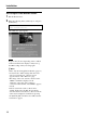
Operation Camera View Operations The Camera View displays the video camera images. Use the screen buttons and icons to switch between cameras and display modes. qd qf 1 qg 2 3 4 5 qh 8 q; 6 7 9 qa qs 1 [ALL] Button Clicking this button switches the monitor screen to the ALL mode (as shown in the above example). In this mode, images from the video cameras connected to the video network station are displayed in two or four partitions.
8 [RELAY] Button Clicking this activates or deactivates the relay output, according to the system administrator settings. qd Site Name This is the name assigned to the overall video network station system. 9 [HOME] Button Returns the video camera to the home position. qf Camera Title This is the title of the video camera. q; [PRESET] Drop-Down List Select a preset camera position by name from this list to set the camera to that fixed position (previously set by the system administrator).
Operation Pan/Tilt/Zoom Control When an EVI-D30/D31/G20/G21 is connected to a serial port on the video network station, camera pan, tilt and zoom can be controlled from the Web page. The monitor screen must be set to the Single mode Camera View: click one of the [CAM1] to [CAM4] buttons, if necessary, to change to the Single mode Camera View. The Pan/Tilt/Zoom control bars and buttons are displayed around the video source image in the Single mode.
Pan/Tilt/Zoom Control Operation Video camera pan, tilt and zoom can be controlled by the following methods. When Using the VISCA Driver Step Clicking a triangle at the top, bottom, left or right of the [Pan]/[Tilt]/[Zoom] control bar causes the video camera to move by a single step, equal to about five degrees of angle. Positioning Clicking a position on the [Pan]/[Tilt]/[Zoom] control bar causes the video camera to be repositioned in a corresponding manner.
Operation Viewing the Alarm List Screen The alarm contents saved in memory can be displayed as a list. Clicking the [ALARM] button in the Camera View displays the Alarm List screen. 1 2 3 Note Depending on which alarm information transfer method (FTP or e-mail) is selected, the order of appearance in the alarm list may differ from that of the actual alarm occurrences. 4 5 6 78 9 1 Alarm Number A serial number (1 to 999) is assigned to each alarm trigger.
Viewing the Alarm Replay Screen Alarm events saved in memory can be replayed as a moving image. 1 Clicking on the desired image on the Alarm List screen switches to the Alarm Replay screen with the selected image displayed as a moving image. 3 2 4 5 6 1 Alarm Information Shows the alarm event trigger, camera number and alarm event date and time. 2 Alarm Image (moving image) Plays back continuous images from before and after the saved alarm event as a moving image.
Operation Viewing Thumbnails – The Alarm Thumbnail Screen Alarm events saved in memory can be displayed as thumbnail images. Click the “Thumbnail Display” icon on the Alarm Replay screen to display images as thumbnails. 1 2 5 3 6 7 4 1 “Paging” Icons Click to change pages when you have multiple pages of thumbnails. 2 Alarm Information Shows the alarm event trigger, camera title and alarm event date and time. 3 Alarm Event Image The image at the moment an alarm event occurred is framed in red.
HSR View Mode Images from the HSR-1/1P/2/2P are displayed in the HSR View. Screen buttons and icons allow switching cameras, controlling pan/tilt/zoom, changing display modes and controlling the HSR-1/1P/2/2P. Also, the screen example below appears when the VISCA driver is set as the pan/tilt driver. Note When multiple users are logged on at the same time, operations of other users may cause the HSR View to change unexpectedly. Check the Users Logged On field to determine if other users are logged on.
Operation 3 Display Partition Buttons Clicking one of these icons selects the image monitor layout. The icons are applicable to the A IMAGE output of the HSR-1/1P/2/2P, and are functional when the [A] button qh is selected, or when the [A/B] button qf and the [A] button 4 are selected. The icons appear as follows when enabled for use. qa Connection Status Shows the type of HSR unit (HSR-1/1P or HSR-2/2P) connected to the video network station.
qk [SEQ] Button Clicking this button controls the automatic image switching function of the HSR-1/1P/2/2P, in which the image from each camera is displayed sequentially, switching from one camera to the next at preset intervals. Click the button again to cancel. HSR-1/1P/2/2P Control The HSR-1/1P/2/2P is controlled from the [HSR CONTROL] page, displayed by clicking the [CTR] button in the HSR View. Functions specific to the HSR-1/1P and HSR-2/2P are described below.
Basic Administration Basic Administration Log File Information Recently executed commands are recorded in the log file on the video network station. The log file is used to check whether a special event was executed, such as whether a command was issued before or after an alarm occurred. It is also used as a troubleshooting tool to resolve operational problems.
Resetting to Factory Defaults Two procedures are available to return the video network station to its factory default settings: one using the RESET switch on the unit, and the other by remotely accessing the “Administration Overview” page from the network. Resetting to Factory Defaults from the Administration Overview Page 1 Display a monitor screen in the Web browser, and click the [Admin] button. The “Administration overview” page appears. 2 Click the [Network Station] icon.
Basic Administration Simultaneous Alarm Input to the HSR-1/1P/2/2P and Video Network Station Alarm Memory When alarm recording is initiated by input of an alarm signal to the HSR-1/1P/2/2P, if the alarm signal is sent from the HSR-1/1P/2/2P to the video network station, the alarm function of the video network station acts simultaneously with the HSR-1/1P/2/2P.
HSR-1/1P/2/2P Settings Video Network Station Settings On the “Administration overview” page, select the “HSR” icon first, and then the “SETUP” icon to make settings on the SETUP MENU page. Items not mentioned below should be set according to the operating environment. On the “Administration overview” page, select [Application] with the “Layout and Application Wizard” (page 13), and set the following items. Items not mentioned below should be set according to the operating environment.
Basic Administration If You Suspect a Problem If you notice a symptom that leads you to suspect the video network station may be broken, please check the following items before contacting your Sony Service Center. Symptom Possible Cause Remedy No access from Web browser The IP address assigned to this unit may have already been assigned to another device.
Lithium Battery Replacement The lithium battery lasts about two years with normal use.* When the battery is depleted, the data and time settings are lost. Contact your Sony Service Center to have the battery replaced (for a charge). *Presuming the power is normally kept on. If the power is regularly turned off, battery life can be expected to be about one year. Actual battery life depends on the operating conditions.
Basic Specifications Basic Specifications Operating Voltage 12 V AC Power Consumption 5.5 W Operating Temperature 5 to 40 ºC Weight Approx. 0.8 kg (excluding AC adapter) External Dimensions 146 × 41.5 × 223.5 mm (WHD) VIDEO IN Terminals (BNC) × 4 VBS, VS signal: 1.0 Vp-p ±0.2 V with 75-Ω/Hi-Z termination. NTSC and PAL formats autodetected S-VIDEO Terminal (4-pin) × 1 Y signal: 1.0 Vp-p ±0.2 V @ 75Ω C signal: 0.28 Vp-p ±0.
RS-232 Serial Interface Terminal Pin Out 1 2 6 3 7 4 8 5 • NC = no connection - - A3 C3 A4 C4 B 1 2 3 4 5 6 7 A 8 Pin No.
Basic Specifications Alarm Inputs CGI/Generic Driver Commands Four photocoupler inputs are provided for alarm inputs. Alarm signals can be connected to any of the inputs as follows. For details on how to make settings, refer to “Generic Driver Settings” on page 25. To use the electrically isolated inputs, the connected device must have 5 to 20-V DC output, connected as follows. Inside server← →Outside server Alarm Device Approx. 4.
z Pan Tilt and Zoom Control and Preset Position To control the Pan, Tilt, and Zoom behavior of a Sony camera, the following PTZ control URL is used. Method: GET/POST Syntax: control PTZ behavior http:///cgi-bin/ control?=[&= ... ] = Values riris= -999 - 999 Moves iris. Positive values means iris open and negative values means iris close. Only used for Kalatel.
Basic Specifications z Controlling and Monitoring (Relay, 4 digital inputs) Method: GET/POST Syntax: input http:///cgi-bin/io/ input.cgi?=[&= ...] Example: Set output 1 on http://myserver/cgi-bin/io/ output.cgi?action=1:/ Example: Set two 300 ms pulses with 500 ms delay between the pulses on output 1 http://myserver/cgi-bin/io/ output.cgi?action=1:/300\500/300\ Example: Wait 1 second before setting output 1 on http://myserver/cgi-bin/io/ output.
x Generic Driver The HTTP Generic driver is enabled by selecting the Generic checkbox in Serial Port 1 (or 2) settings. To enable TCP Generic driver a TCP port number must be selected in the Generic Driver settings. z HTTP Generic driver Method: GET/POST Syntax: control serial port http:///cgi-bin/ control?=[&= ...
Settings List Settings List Settings that can be changed with each wizard and dialog box are as follows. Asterisks (*) denote items that can be set with the “First Time Installation Wizard”.
Warranty Card and After Sales Service Warranty Card • The warranty card should be provided with the server at the time of purchase. • Please read the terms on the card, fill in any required items, and keep it in a safe place. After Sales Service If a problem arises, first check for the cause Refer to this operating manual for the possible causes and remedy.
Français AVERTISSEMENT Afin d’éviter tout risque d’incendie ou d’électrocution, ne pas exposer cet appareil à la pluie ou à l’humidité. Afin d’écarter tout risque d’électrocution, garder le coffret fermé. Ne confier l’entretien de l’appareil qu’à un personnel qualifié. ATTENTION Il y a danger d’explosion s’il y a remplacement incorrect de la batterie. Remplacer uniquement avec une batterie du même type ou d’un type équivalent recommandé par le constructeur.
Table des matières Caractéristiques de Video Network Station .................. 54 Nomenclature ................................................................... 55 Panneau avant .......................................................................55 Panneau arrière ......................................................................56 Exemples d’applications système ................................. 57 Installation ........................................................................
Caractéristiques de Video de Network Station Caractéristiques Video Network Station Cet appareil est une station de réseau vidéo qui distribue des images CCTV en temps réel via LAN ou Internet. Contrôle simple par un réseau • En attribuant une adresse IP à cet appareil, la vidéo en direct peut être contrôlée via les navigateurs Web standards sur le PC client. • L’appareil peut être réglé et contrôlé à partir de la page Web.
Nomenclature Panneau avant 6 S VIDEO POWER STATUS NETWORK VIDEO 1 VIDEO 2 7 VIDEO 3 VIDEO 4 75Ω OFF 1234 75Ω ON 1 2 34 5 1 Borne d’entrée S VIDEO (4 broches) Les sources vidéo fournissant des signaux Y/C sont entrées ici. La borne d’entrée VIDEO 1 n’est pas utilisable lorsque cette borne est utilisée. 2 Indicateur STATUS Indique l’état de fonctionnement de l’appareil. Couleur Etat du serveur Orange L’autotest s’exécute après la mise sous tension.
Nomenclature Panneau arrière 1 2 ~ ~ 1 AC IN (12V) 2 A3 C3 A4 C4 B 3 4 5 6 7 COM 2 ETHERNET 10 /100 – A1 C1 A2 C2 RELAY 6 1 Borne d’entrée AC IN (12 V) L’adaptateur AC fourni se connecte ici. 2 Borne COM 1 (9-broches D-Sub) Les EVI-D30/D31/G20/G21 ou HSR-1/1P/2/2P peuvent être raccordés ici. Le EVI-D30/D31/G20/G21 se raccorde à l’aide du câble VISCA et le HSR-1/1P/2/ 2P à l’aide du câble RS-232C. 3 Borne COM 2 (9-broches D-Sub) Les EVI-D30/D31/G20/G21 ou un modem peuvent être raccordés ici.
Exemples d’applications système • Il est possible de raccorder jusqu’à quatre sources vidéo au serveur. • La qualité d’image la plus élevée peut être distribuée via S-video. Utilisation de EVI-D30/D31 Raccorder un EVI-D30/D31 à la video network station via la borne COM1 ou COM2 pour pouvoir contrôler la panoramique, l’inclinaison et le zoom à partir d’un ordinateur sur le réseau.
Installation Installation Après avoir raccordé les sources vidéo et le réseau à la video network station, mettre l’appareil sous tension et régler l’adresse 0 é A propos de l’environnement de fonctionnement L’environnement de fonctionnement suivant est requis pour régler le serveur et visionner les images. • Ordinateur : 400-MHz Pentium III avec 64-MB de RAM ou plus • Système d’exploitation : Windows 98, Windows Me, Windows NT 4.0 SP5 ou ultérieur ou Windows 2000 • Navigateur Web : Internet Explorer 5.0, 5.
Attribution de l’adresse IP 1 Entrer les commandes suivantes à une invite MSDOS (ou une invite de commande) dans un ordinateur du réseau : arp -s z Conseil Par exemple, les entrées peuvent être similaires à ce qui suit : arp -s 192.36.253.
Installation Accès à la Video Network Station 1 2 Lancer le navigateur Web. Entrer ce qui suit dans la zone [Adresse] et appuyer sur la touche Enter. http:/// La page “Welcome” apparaît. Remarque La réponse peut être lente en fonction du réseau. Si l’affichage de l’écran tarde, arrêter le chargement URL et essayer à nouveau d’obtenir l’accès.
Réglages Ce chapitre décrit comment régler la video network station pour divers types de système et d’applications. Les réglages de la video network station sont effectués en utilisant Internet Explorer 5 ou 5.5. 1 Cliquer sur l’icône “First Time Installation Wizard” dans la page “Welcome” puis sur [OK] lorsque le message de confirmation apparaît. L’assistant apparaît. 2 Suivre les instructions à l’écran de l’assistant pour effectuer les réglages.
Réglages Accès à la page Administration Overview Cliquer sur le bouton (Admin) pour afficher la page “Administration overview”. Une fois les réglages de base effectués avec “First Time Installation Wizard”, tous les réglages et la gestion de la video network station sont effectués dans la page “Administration overview”. 1 Lancer le navigateur Web et entrer ce qui suit dans la zone [Adresse] et appuyer sur Enter. http:/// L’écran moniteur apparaît.
Réglage de l’écran moniteur et de la fonction alarme L’icône (Application Design) est utilisée pour configurer l’affichage de l’écran moniteur et pour déterminer le fonctionnement de la video network station lorsqu’une alarme se produit. Cliquer sur l’icône “Application Design” pour afficher l’écran suivant.
Réglages Réglages Alarm Réglage Number of PRE alarm images Réglage Description Alarm Buffer, Overwrite Une capacité prédéterminée de mémoire est utilisée pour enregistrer des images avant et après une alarme. Si la quantité d’images dépasse la capacité autorisée, sélectionner s’il faut enregistrer sur les images sauvegardées précédemment par ordre d’ancienneté. Sélectionner [ON] (écrasement) ou [OFF] (pas d’écrasement).
Remarque Réglage • Lorsque la fonction d’alarme est activée, il n’est pas possible de régler [Quality] pour les images vidéo sur [Hyper]. Pour les détails sur les réglages d’image vidéo, voir “Réglages de image vidéo” (page 76). • Les alarmes qui surviennent pendant une écriture dans la mémoire d’alarme ne sont pas enregistrées dans la mémoire.
Réglages Réglages de réseau L’icône (Network Settings) est utilisée pour les réglages relatifs au protocole de réseau de support. Cliquer sur l’icône “Network Settings” pour afficher l’écran suivant. Réglage Description TCP/ BOOTP* IP Permet au protocole BOOTP de télécharger automatiquement l’adresse IP. Internet Address Entrer l’adresse IP de la video network station. Default Router Entrer l’adresse du routage par défaut du réseau. Subnet Mask Entrer le masque sous net du réseau.
Administration de système et sécurité L’icône (Network Station) est utilisée pour configurer la sécurité de la video network station ou l’administrateur du système. Cliquer sur “Network Station” affiche l’écran suivant. Les articles de réglage sont indiqués dans le tableau suivant. A la fin du réglage, cliquer sur l’icône “Save”. L’exactitude de l’horloge interne est de ±120 secondes/mois ou moins.
Réglages Changement du mot de passe de l’administrateur du système Remarque Les fonctions protégées par un mot de passe du HSR-1/1P/2/2P tel que le verrouillage et le déverrouillage de touche sont accessibles de la page “HSR CONTROL”. L’autorisation d’accès à la page “HSR CONTROL” doit être considéré avec précaution. Remarque Au départ d’usine de la video network station, le nom de l’utilisateur et le mot de passe de l’administrateur du système sont réglés sur “root” et “pass”.
Affichage des remarques sur la sortie Cliquer sur le bouton (View Release Notes) pour ouvrir une nouvelle fenêtre et afficher la page “Release Notes”. La page “Release Notes” donne des informations sur la version du logiciel et du progiciel de la video network station. Réglages du port série Les icônes (COM1 et COM2) représentent les ports série de la video network station.
Réglages Réglage Options Description Purpose Modem (affiché seulement pour COM2) A sélectionner si un modem est raccordé au port. Si elles sont sélectionnées, les icônes “Modem” et “ISP” indiquées dessous sont affichées. Generic A sélectionner si un pilote CGI/Generic est utilisé. Si elle est sélectionnée, • Lorsque [HSR] est sélectionné, la page “Sony HSR Settings” apparaît. Se reporter à “Réglage de HSR-1/1P/2/2P” en page 72. • Lorsque “Modem” est sélectionné, la page “Modem Settings” apparaît.
z Conseil Sélectionner [Kalatel] lors de la connexion d’appareils qui accepte des protocoles Kalatel. 6 Cliquer sur le bouton [Apply]. Les réglages sont appliqués et l’icône “Preset Positions” est ajoutée à la caméra vidéo dont le numéro ID a été réglé. 7 Pour régler les positions préréglées de la caméra vidéo, aller à “Réglage de la position préréglée de la caméra panoramique/inclinaison” ci-dessous ; sinon cliquer sur le bouton [Close] pour finir les réglages.
Réglages 2 Observer l’image échantillon de la caméra vidéo tout en réglant la position de la caméra l’aide des barres de contrôle [Pan], [Tilt] et [Zoom]. Cliquer sur l’icône “HSR” pour afficher la page “Sony HSR Settings”. z Conseil • Lorsque [Kalatel] est sélectionné comme pilote panoramique et inclinaison, les boutons de commande [FOCUS] et [IRIS] apparaissent.
Précautions de réglage HSR-1/1P/2/2P • Il faut toujours fermer les écrans de menu, recherche d’heure et recherche d’alarme du HSR1/1P/2/2P avant d’effectuer les réglages. Lorsque l’écran de menu, de recherche d’heure ou de recherche d’alarme est affiché dans le HSR-1/1P/2/ 2P, le message d’erreur “The menu settings on the HSR cannot be made. Check the statuses of the connected equipment.
Réglages • Procédure de réglage du mode d’enregistrement Pour régler le mode d’enregistrement, ouvrir les pages “RECORDING MODE 1” - “RECORDING MODE 5” dans la page “RECORDING FUNCTION” et régler les éléments suivants : – [CAMERAS] – [TAPE LENGTH] – [IMAGE QUALITY] – soit [TIME MODE] soit “RECORDING CYCLE” Le HSR-1/1P/2/2P calcule automatiquement la valesÄ de [TIME MODE] ou de “RECORDING CYCLE” entré lorsque le bouton “SET” est cliqué.
Réglage du modem Réglage ISP (Internet Service Provider) L’icône (Modem) est affiché lorsque [Modem] est sélectionné pour l’usage du port série. Lorsqu’un modem est raccordé la video network station et si l’icône “Modem” n’apparaît pas côté de l’icône “COM2”, se reporter à “Réglages du port série” en page 69 pour réinitialiser l’utilisation du port série. L’icône (ISP) est affiché lorsque [Modem] est sélectionné pour l’utilisation du port série.
Réglages Réglages du pilote Generic L’icône (Generic) apparaît lorsque l’utilisation du port série est réglée sur [Generic]. Si elle ne s’affiche pas, se reporter à “Réglages du port série” en page 69 et réinitialiser l’utilisation du port série. 1 Cliquer sur l’icône “Generic”. La page “Generic Driver Settings” apparaît. Réglage de l’entrée vidéo Les icônes (Video) indiquent les sources vidéo raccordées aux bornes d’entrée VIDEO 1 à VIDEO 4.
3 Cliquer sur l’icône “Save”. Les réglages sont enregistrés. Réglages de l’image vidéo Cliquer sur l’icône (Image settings) pour afficher la boîte de dialogue “Image Settings for Video 1”. Les articles pouvant être réglés sont les suivants : Réglage Description Display date & time on image Cocher cette case pour afficher la date et l’heure avec l’image vidéo. Display text on image Cocher cette case pour afficher un texte tel que le titre de la caméra avec l’image vidéo.
Réglages Réglage de la méthode de modulation d’entrée vidéo Cliquer sur l’icône (Video Input/Modulation) pour afficher la boîte de dialogue “Input/Modulation for Video 1”. Si seule la source vidéo actuelle est à régler, sélectionner [Video 1’s] dans la liste déroulante [Apply detection and settings to]. Si toutes les sources vidéo doivent être réglée en même temps, sélectionner [All Videos’]. Sélectionner, ensuite, la méthode de modulation pour l’entrée vidéo : réglage manuel ou détection automatique.
Fonctionnement Ce chapitre décrit comment contrôler les images distribuées par le serveur. L’écran moniteur apparaît. z Conseil • Les fonctions de la video network station ainsi que les vues et fonctionnement de l’écran moniteur sont réglés par l’administrateur du système en fonction des conditions du système de surveillance. Les fonctions et les écrans montrés dans ce chapitre peuvent être différents de ceux du système actuellement utilisé.
Fonctionnement Opérations Camera View Camera View affiche les images de la caméra vidéo. Utiliser les boutons et icônes de l’écran pour commuter entre les modes caméras et affichage. qd qf 1 qg 2 3 4 5 qh 8 q; 6 7 9 qa qs qj 1 Bouton [ALL] Cliquer sur ce bouton pour passer l’écran moniteur sur le mode ALL (tel qu’indiqué dans l’exemple cidessus). Dans ce mode, les images des caméras vidéo raccordées à la video network station sont affichées en deux ou quatre partitions.
7 Indicateur de sortie relais Lorsque la sortie relais est active, cet indicateur s’allume en bleu. Lorsqu’elle est inactive, il s’allume en gris. 8 Bouton RELAY Cliquer dessus pour activer ou désactiver la sortie relais en fonction des réglages de l’administrateur système. 9 Bouton [HOME] Remet la caméra vidéo sur la position initiale.
Fonctionnement Contrôle Panoramique/Inclinaison/Zoom Lorsqu’un EVI-D30/D31/G20/G21 est raccordé à un port série de la video network station, la panoramique, l’inclinaison et le zoom de la caméra peuvent être contrôlés à partir de la page Web. L’écran moniteur doit être réglé sur le mode simple Camera View : Les barres de commande Pan/Tilt/Zoom sont affichées autour de l’image de source vidéo dans le mode simple.
Opération de contrôle Panoramique/ Inclinaison/Zoom La panoramique, l’inclinaison et le zoom peuvent être contrôlés par les méthodes suivantes. Lors de l’utilisation du pilote VISCA Etape Cliquer un des triangles en haut, en bas, à gauche ou à droite de la barre de contrôle [PAN]/[TILT]/ [SOOM] pour déplacer la caméra vidéo d’un angle approximatif de cinq degrés. Positionnement Cliquer sur une position de la barre de contrôle [PAN]/[TINT]/[ZOOM] pour repositionner la caméra vidéo d’une certaine manière.
Fonctionnement Visionnement d’un écran Alarm List Le contenu de l’alarme enregistré dans la mémoire peut être affiché comme liste. Cliquer sur le bouton [ALARM] dans Camera View pour afficher l’écran liste d’alarme. 1 2 Remarque Selon la méthode sélectionnée pour le transfert des informations d’alarme (FTP ou e-mail), l’ordre d’apparition des alarmes dans la liste peut être légèrement différent de l’ordre d’apparition réel des alarmes.
Visionnement de l’écran Alarm Replay Les alarmes enregistrées dans la mémoire peuvent être relues en image mobile. Cliquer sur l’image souhaitée 1 dans l’écran Alarm List pour passer dans l’écran Alarm Replay avec l’image sélectionnée affichée comme image mobile. 3 2 4 5 6 1 Information d’alarme Montre le déclencheur d’alarme, le numéro de la caméra ainsi que la date et l’heure de l’alarme.
Fonctionnement Visionnement des miniatures – Ecran miniature d’alarme Les alarmes enregistrées en mémoire peuvent être affichées comme images miniatures. Cliquer sur l’icône “Thumbnail Display” dans l’écran de relecture d’alarme pour afficher les images en miniature. 1 2 5 3 6 4 7 1 Icônes “Paging” Cliquer pour changer les pages lorsqu’il y a plusieurs pages de miniatures. 2 Information d’alarme Montre le déclencheur d’alarme, le titre de la caméra ainsi que la date et l’heure de l’alarme.
Mode HSR View Les images du HSR-1/1P/2/2P sont affichées dans HSR View. Les boutons et les icônes d’écran permettent de commuter les caméras, contrôler la panoramique/inclinaison/zoom, changer les modes d’affichage et contrôler le HSR-1/1P/2/2P. De même, l’exemple d’écran ci-dessous apparaît lorsque le pilote VISCA est réglé comme pilote Pan/Tilt.
Fonctionnement 3 Boutons Display Partition Cliquer sur l’une de ces icônes pour sélectionner la disposition du moniteur d’image. Les icônes sont applicables à la sortie A IMAGE du HSR-1/1P/2/2P et sont fonctionnelles lorsque le bouton [A] qh est sélectionné ou lorsque le bouton [A/B] qf et le bouton [A] 4 sont sélectionnés. Les icônes apparaissent comme suit lorsqu’elles sont activées pour l’utilisation. HSR View peut afficher quatre à seize partitions.
qj Bouton [CTR] Cliquer sur ce bouton pour afficher la page “HSR CONTROL” dans une nouvelle fenêtre pour contrôler le HSR-1/1P/2/2P. Se reporter à “Contrôle de HSR-1/ 1P/2/2P” ci-dessous pour les détails. qk Bouton [SEQ] Cliquer sur ce bouton pour contrôler la fonction de commutation d’image automatique du HSR-1/1P/2/ 2P,dans laquelle l’image de chaque caméra est affichée en séquence, passant d’une caméra à une autre à des intervalles préréglés. Cliquer de nouveau sur le bouton pour annuler.
Administration de base de Administration base Informations sur le fichier journal Les commandes récemment exécutées sont enregistrées dans le fichier journal de la video network station. Le fichier journal est utilisé pour vérifier si un évènement spécial a été exécuté, tel que l’exécution d’une commande avant ou après qu’une alarme ne se produit. Il est aussi utilisé comme outil de dépannage pour résoudre les problèmes opérationnels.
Réglages par défaut d’usine Deux procédures sont disponibles pour remettre la video network station à ces réglages par défaut au départ d’usine : l’une utilise le commutateur RESET sur l’appareil et l’autre par l’accès à distance à la page “Administration Overview” dans le réseau. Remarque La procédure suivante remet tous les réglages, y compris l’adresse IP du périphérique à leurs valeurs par défaut d’usine.
Administration de base Entrée simultanée d’alarme dans le HSR-1/1P/2/2P et mémoire d’alarme de la Video Network Station Lorsque l’enregistrement d’alarme est initié en entrant un signal d’alarme dans le HSR-1/1P/2/2P et que ce signal est envoyé du HSR-1/1P/2/2P à la video network station, la fonction d’alarme de la video network station agit simultanément avec le HSR-1/1P/ 2/2P.
Réglages HSR-1/1P/2/2P Réglages de la Video Network Station Dans la page “Administration overview”, sélectionner tout d’abord l’icône “HSR”, puis l’icône “SETUP” pour effectuer les réglages dans la page SETUP MENU. Les articles non mentionnés ci-dessous doivent être réglés en fonction de l’environnement d’exploitation. Dans la page “Administration overview”, sélectionner [Application] avec “Layout and Application Wizard” (page 63) et régler les articles suivants.
Administration de base En cas de problème Si vous suspectez une panne de la video network station, prière de vérifier les points suivants avant de contacter le service après-vente Sony. Symptôme Cause possible Remède Aucun accès du navigateur Web L’adresse IP attribuée à cet appareil peut être déjà attribuée à un autre périphérique.
Remplacement de la batterie au Lithium La batterie au lithium dure environ deux ans avec une utilisation normale.* Lorsque la batterie est considérablement réduite, les réglages de date et heure sont perdus. Contacter le service après-vente Sony pour remplacer la batterie (pour la charge). *En assumant que l’appareil est constamment mis sous tension. Si l’appareil est régulièrement mis hors tension, la durée de vie de la batterie sera d’environ un an.
Spécifications de base de Spécifications base Tension de fonctionnement AC 12 V Consommation électrique 5.5 W Température de fonctionnement de 5 à 40 ºC Poids Env. 0.8 kg (excepté l’adaptateur AC) Dimensions externes 146 × 41.5 × 223.5 mm (LHP) Bornes VIDEO IN (BNC) × 4 Signal VBS, VS : 1.0 Vp-p ±0.2 V avec une terminaison 75-Ω/Hi-Z. Les formats NTSC et PAL sont auto-détectés. Borne S-VIDEO (4-broches) × 1 Signal Y : 1.0 Vp-p ±0.2 V @ 75Ω Signal C : 0.28 Vp-p ±0.
Brochage de borne d’interface sérielle RS232 1 2 6 3 7 4 8 5 9 La largeur du connecteur ne doit pas dépasser 32 mm. Brochage du connecteur de bloc de borne I/O - - A3 C3 A4 C4 B 1 2 3 4 5 6 7 A 8 No.
Spécifications de base Remarque Entrées d’alarme Quatre entrées photocoupleur sont fournies pour les entrées d’alarme. Les signaux d’alarme peuvent être raccordés à n’importe quelle entrée comme suit. Pour utiliser les entrées isolées électriquement, l’appareil raccordé doit avoir une sortie DC de 5 à 20 V, raccordée comme suit. Insérer une diode de protection lors de la connexion d’une charge conductrice, tel qu’un relais, aux broches de sortie d’alarme 15 et 16.
z Pan Tilt and Zoom Control and Preset Position To control the Pan, Tilt, and Zoom behavior of a Sony camera, the following PTZ control URL is used. Method: GET/POST Syntax: control PTZ behavior = Values riris= -999 - 999 Moves iris. Positive values means iris open and negative values means iris close. Only used for Kalatel. focusrel= far, farmore, near, nearmore irisrel= open, Adjusts the iris gradually. Only close, used for Kalatel.
Spécifications de base z Controlling and Monitoring (Relay, 4 digital inputs) Method: GET/POST Syntax: input http:///cgi-bin/io/ input.cgi?=[&= ...] Example: Set output 1 on http://myserver/cgi-bin/io/ output.cgi?action=1:/ Example: Set two 300 ms pulses with 500 ms delay between the pulses on output 1 http://myserver/cgi-bin/io/ output.cgi?action=1:/300\500/300\ Example: Wait 1 second before setting output 1 on http://myserver/cgi-bin/io/ output.
x Generic Driver The HTTP Generic driver is enabled by selecting the Generic checkbox in Serial Port 1 (or 2) settings. To enable TCP Generic driver a TCP port number must be selected in the Generic Driver settings. z HTTP Generic driver Method: GET/POST Syntax: control serial port http:///cgi-bin/ control?=[&= ...
Liste des des réglages Liste réglages Les réglages pouvant être modifiés avec chaque message et boîte de dialogue sont les suivants. L’astérisque (*) indique les articles pouvant être réglés avec “First Time Installation Wizard”.
Carte de garantie et service après-vente Carte de garantie • La carte de garantie doit être fournie avec le serveur au moment de l’achat. • Prière de lire les termes de cette carte, remplir les points nécessaires et la garder dans un endroit sûr. Service après-vente En cas de problème, chercher d’abord la cause Se reporter à ce manuel de fonctionnement pour les causes possibles et les solutions.
Sony Corporation Printed in Sweden