4-137-706-01(1) HD Color Camera Operating Instructions Before operating the unit, please read this manual thoroughly and retain it for future reference.
WARNING To reduce the risk of fire or electric shock, do not expose this apparatus to rain or moisture. To avoid electrical shock, do not open the cabinet. Refer servicing to qualified personnel only. For the customers in the U.S.A. This equipment has been tested and found to comply with the limits for a Class A digital device, pursuant to Part 15 of the FCC Rules.
Function-assignable switches Overview The HXC-100 is a 2/3-type high-definition portable video camera equipped with CCD units for 2,200,000 pixels, which can be used as a standalone camera as well as in a studio in combination with the HXCU-100 Camera Control Unit. The camera has buttons to which various functions can be assigned on the side panel and the rear.
Knee saturation Versatile choices of viewfinders Change of hue and decrease in chroma that occur in highlighted areas can be compensated. This enables reproduction of natural skin tones under strong lighting. Multiformat monochrome CRT viewfinders, HDVF-200 (2type) and HDVF-550 (5-type) can be selected for use in studio and portable systems. Color LCD viewfinders, HDVF-C35W (3.5-type), HDVFC730W (6.3-type), and HDVF-C950W (9-type), are also selectable to cover various applications.
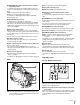
System operation example (with a Camera Control Unit) HDVF-550/C730W/C950W Viewfinder Picture Monitor Microphone Waveform Monitor HDVF-200/C35W Viewfinder VF attachment shoe a) CAC-12 Microphone Holder BNC Return video input Intercom headset HXC-100 Zoom Lens (for ENG/EFP) BNC Video router Sync input Prompter video input Video output HD-SDI/SD-SDI/VBS Triax cable b) to router/switcher “Memory Stick” Power supply for a script light DC 12 V (Max. 0.
f Lens mount cap The cap can be removed by moving the lens fixing lever upward. Always keep the lens mount covered with this cap when a lens is not attached. g Lens fixing lever Move the lever down to secure the lens in the lens mount. For details, see “Attaching a Lens” (page 10). h Viewfinder front-rear position lock lever The viewfinder position can be adjusted forward or backward when the lock is released by the lever.
e AUTO W/B BAL (white and black balance automatic adjustment) switch To automatically adjust white and black balance when the camera is used in stand-alone status without connecting to a CCU. WHT: To automatically adjust white balance. BLK: To automatically adjust black balance. For details, see “Adjusting the Black Balance and White Balance” (page 13). f INTERCOM LEVEL control To adjust the intercom/earphone volume level.
Note The RET 1 button has priority over the RET (2/3/4) button if both buttons are pressed. c DISPLAY/MENU switch This switch functions the same as the DISPLAY/MENU switch on the front (page 6). d ASSIGNABLE button You can assign a function with ASSIGNABLE REAR on the page of the OPERATION menu. e Menu control knob (rotary encoder) This knob functions the same as the menu control knob on the front (page 6).
f REMOTE connector (8-pin) For connection to an RM-B150/B750 Remote Control Unit or RCP-700/900-series Remote Control Panel. Installation Note When a CCU is used in combination, this connector functions as the trunk signal input/output. Do not connect any remote control device to this connector. g TEST OUT connector (BNC type) To output an analog signal.
4 Adjust the length by pulling down the end of the belt. B 1 INCOM RET 1 2 3 1 Attaching a Lens For information on handling lenses, refer to the operation manual for the particular lens B VF A 1 LE NS SHUT RET 5 1 2 3 4 5 C 2 TER WHT OFF ON BLK SEL INETE RCOM LEVE L Loosen the viewfinder left-right positioning ring and slide the viewfinder in the direction of arrow A. The viewfinder stopper B automatically pops down.
When the DISPLAY/MENU switch is set to DISPLAY Items set to ON using the menu or related switches will be displayed. 1 2 0dB 1/125 7 9 0 F5.6 qa !ND !FAN !EXT !FORMAT 3 F255 12.5V 5600 1 W:A 8 FORMAT :1080-59.94i ASSIGNABLE1 :5600K ASSIGNABLE2 :OFF ASSIGNABLE REAR:OFF 4 5 3 EX Z55 TALK 6 1 2 :2 :MAX :ON :1080-59.94i a Assignable button indication The functions assigned to the assignable buttons are indicated.
To attach a microphone, using a CAC-12 When attaching a long-type microphone, such as an ECM674/678, use an optional CAC-12 Microphone Holder. 1 1 Remove the front screw-hole cover on the top then 2 fix the CAC-12 in place with the two screws (+B4×8) supplied with the CAC-12. 2 2 CAC-12 1 Tripod adaptor 1 Platform 1 2 Loosen the screw to open the CAC-12 and attach the microphone.
Original position Preparatory Settings Pin Adjusting the Black Balance and White Balance In order to maintain high picture quality when using the camera, it is necessary to set the black balance and white balance appropriately for the conditions. Adjusting the Shoulder Pad Position 1/ You can shift the shoulder pad in the range of 28 mm (1 8 inches). This adjustment helps you get the best balance for shooting with the camera on your shoulder.
To adjust the white balance 1 Select the built-in filter according to the lighting conditions with the filter select knob (1: Clear, 2: 1/4 ND, 3: 1/16 ND, 4: 1/64 ND). After about one second, the message “AWB: OK” will be displayed, and the adjustment process will complete. The adjusted value will be automatically stored in the selected memory (A or B). Note When using a zoom lens with automatic iris control capability, hunting1) may occur. Adjust the lens’ iris gain control (labeled IG, IS, S, etc.).
Note With artificial lighting, particularly fluorescent lights and mercury vapor lamps, the brightness appears to be constant, but in fact the strength of the red, green, and blue components varies with the power supply frequency. This phenomenon is known as “flicker.” When using the electronic shutter under these lighting conditions, there are certain cases in which the flicker is more noticeable. In particular, color flicker is evident when the power frequency is 60 Hz.
2 Place the supplied flange focal length adjustment chart approximately 3 meters from the camera and adjust the lighting to get an appropriate video output level. 4 Rotate the menu control knob to align the pointer to OPERATION and push on the knob. The CONTENTS page of the OPERATION menu is displayed. CONTENTS About 3 meters (10 ft) 3 4 5 6 7 8 9 Loosen the Ff (flange focal length) ring lock screw. 5 With either manual or power zoom, set the zoom ring to telephoto. Set the zoom ring to wide angle.
8 To finish the adjustments, set the DISPLAY/MENU switch to OFF to exit Menu mode. To use the area marker Setting AREA MARKER to ON displays the detection area of the focus as a marker on the viewfinder screen. You can set the size and position of the detection area with the menu items below. SIZE: The size of the detection area can be changed. (If the area size is too large, both the subject and the background are included in the area, making the indicator display easily deviate from the subject.
To output as HD-SDI Menu page Item Setting SDI OUT ACTIVE OUTPUT MAIN To output as SD-SDI Menu page Item Setting SDI OUT ACTIVE DOWN CONVERTER ACTIVE OUTPUT SIGNAL MAIN OUTPUT SD-SDI To output as VBS Note With the settings for outputting the same image as that on the viewfinder, the output will be obtained in 1080i, even if the format setting is 720P.
Basic Procedure for Shooting • Settings for the output signals from the camera (page 17) • Flange focal length setting (page 15) 4 For viewfinder settings, refer to the operation manual for the viewfinder. Note When an HXCU-100 Camera Control Unit or an external control device, such as an RCP-series Remote Control Panel, is connected, the white balance, black balance and shutter adjustments are controlled from the external device, and the controls on the camera are disabled.
Menus The menus displayed on the viewfinder screen enable various settings of the camera. The following controls are used to operate the menus. To enter Menu mode, you can use the DISPLAY/MENU switch either on the side or on the rear operation panel. The menu control knob at the low on the front panel and that on the rear operation panel function the same. Rotate the knob to select menu items or values and push on it to register (enter) the selection.
To reset a changed value If you press the STATUS/ CANCEL switch toward CANCEL before pushing on the menu control knob, the setting will be returned to its previous value. To interrupt settings Set the DISPLAY/MENU switch to OFF to turn off the menu screen display. The setting operation can be restarted by setting the DISPLAY/MENU switch back to MENU. If the screen can be scrolled, arrows will indicate the direction for scrolling. CONTENTS Pointer 00 TOP 01. 02.<'!'IND> 03. 04.
Menu page title If the USER MENU CUSTOMIZE menu has been used before, the page last accessed appears. USER menu Source menu / page No. No.
To change the order of items on a page 1 2 3 2 Move the pointer to the item to be moved then push on the menu control knob. The EDIT FUNCTION screen appears. Select MOVE then push on the menu control knob. The previously displayed page appears again. xx Move the pointer to the position where you wish to move the item then push on the menu control knob.
To change the order of pages on the USER menu 1 2 3 Display the EDIT PAGE screen of the USER MENU CUSTOMIZE menu. Turn the menu control knob to move the pointer to the page that you wish to move. The EDIT FUNCTION screen appears. Select MOVE then push on the menu control knob. The EDIT PAGE screen appears again. Move the pointer to the position where you wish to move the page then push on the menu control knob. xx ITEM MOVE ESC 01. 02. 03. c 04. 05.
Page title Page No. Item <'!' IND> 02 (U05) [IND]: Activate/deactivate the '!' indication (page 11). [NORMAL]: Specify the conditions under which the ‘!’ indication is not to be displayed even if [IND] is ON. (By specifying the standard or normal conditions here, non-standard or abnormal conditions can be found with the ‘!’ indication on the viewfinder.) ND Settings Page title Page No.
Page title Page No. Item Settings Page title Page No. Item 05 (U03) INDICATOR ON, OFF, (EFFECT) (EFFECT): Displayed when EFFECT of is ON.
Page title Page No. Item Settings Page title Page No. Item Settings 10 (U10) LENS VTR S/S Assign a function to the VTR START/STOP switch on the mounted lens.
Page title Page No. PAINT Menu Page title Page No. Item P01 FLARE ON, OFF GAMMA ON, OFF BLK GAM ON, OFF
Page title Page No. Item Settings Page title Page No. P07 K POINT R/G/B/M: –99 to +99 0 K SLOPE R/G/B/M: –99 to +99 0 P11 KNEE ON, OFF KNEE MAX ON, OFF KNEE SAT –99 to +99 0 ON, OFF ON, OFF, (MAT) (MAT): Displayed when GATE of is ON. AUTO HUE Execute by ENTER.
Page title Page No. Item Settings Page title Page No. Item Settings P13 PHASE Select an axis (angle) for which the multimatrix adjustment to be made. 0, 23, 45, 68, 90, 113, 135, 158, 180, 203, 225, 248, 270, 293, 315, 338 P15 See “FILE menu” F02. 1 To store and read scene files (paint data). 5 STANDARD Execute by ENTER. READ (MS→CAM) Execute by ENTER. ALL CLEAR FILE ID Max.
Page title Page No. Item PHASE M04 Select an axis (angle) for which the OHB matrix adjustment to be made. Settings Page title Page No. Item Settings 0, 23, 45, 68, 90, 113, 135, 158, 180, 203, 225, 248, 270, 293, 315, 338
Page title Page No. Item REFERENCE M14 Items other than GENLOCK REFERENCE STATUS are displayed only when no FORMAT CCU PHASE connected. 32 Settings Page title Page No. Item Settings Condition of synchronisation, display only M18 DATE TYPE 1 Y/Mn/D, 2 Mn/D, 3 D/M/Y 4 D/M, 5 M/D/Y, 6 M/D Y: Year Mn: Month (numeric) M: Month (character string) D: Day F NO.
Page title Page No. Item Settings / Default Page title Page No. Item F02 1 To store and read scene files (paint data): When storing a file in camera memory, specify the number for STORE and execute by ENTER. When reading, only specify the number. F04 STORE FILE Execute by ENTER. No. 1 to 17 1 to 16: When using a non-serial lens 17: When using a serial lens NAME Lens file name Changeable only when using a non-serial lens F NO F1.0 to F3.4 F1.
DIAGNOSIS Menu This menu is only for viewing and no setting is made using this menu. Appendices Page title Page No. Item Indication D01 OHB OK, NG DPR OK, NG CD OK, NG TX OK, NG SY OK, NG PS OK, NG Do not subject to severe shocks TG Vx.xxx Damage to the case or internal components may result. AT Vx.xxx VDAP Vx.xxx VSOP Vx.xxx D02 Precautions Note on laser beams Laser beams may damage the CCDs.
Aliasing Message Meaning When fine patterns, stripes, or lines are shot, they may appear jagged or flicker. VF RPN BUSY RPN compensation was attempted from an external device while being operated using the camera menu. Consult Sony service personnel. NO MEMORY STICK A “Memory Stick” operation was attempted with no “Memory Stick” in the slot. MEMORY STICK ERROR An error occurred during access to a “Memory Stick.
product or remove the “Memory Stick.” This may damage the data. Specifications About a “Memory Stick” General Power requirements Terminal 180 V DC, 1.0 A (max.) 12 V DC, 7 A (max.) Write-protect tab Operating temperature −10°C to +45°C (14°F to +113°F) Storage temperature −20°C to +60°C (−4°F to +140°F) Mass Approx. 4.4 kg (9 lb 11 oz) (camera head only) Labelling position Imager • When you set the “Memory Stick” write-protect tab to “LOCK,” data cannot be recorded, edited, or erased.
Supplied accessories Operating instructions (1) CD-ROM (1) Cable clamp belt (1) Switch label (1) Flange focal length adjustment sheet (1) Optional accessories HD Electronic Viewfinder HDVF-200 (2-type, monochrome) HDVF-550 (5-type, monochrome) HDVF-C35W (3.5-type, color) HDVF-C730W (6.
Menu Tree OPERATION VF DISPLAY (01) EX ZOOM DISP FOCUS ND 5600K IRIS WHITE GAIN SHUTT BATT RETURN TALK MESSAG ‘ ! ’ IND (02) ND WHITE 5600K GAIN SHUTT FAN EXT FORMAT VF MARKER (03) MARKER CENTER SAFETY ZONE EFFECT ASPECT MASK SAFETY VF DETAIL (04) VF DETAIL CRISP FREQUENCY FAT MODE FLICKER AREA ZOOM LINK COLOR DETAIL PEAK COLOR CHROMA LEVEL FOCUS ASSIST (05) INDICATOR MODE LEVEL GAIN OFFSET AREA MARKER SIZE POSITION POSITION H POSITION V 38 Appendices ZEBRA (06) ZEBRA ZEBRA1 LEVEL WIDTH ZEBRA2 CURSOR (07
PAINT SW STATUS (P01) FLARE GAMMA BLK GAM KNEE WHT CLIP DETAIL LVL DEP SKIN DTL MATRIX VIDEO LEVEL (P02) WHITE BLACK FLARE GAMMA V MOD FLARE V MOD D.
FILE TEST OUT (M10) OUTPUT (PWR SAVE) VBS-OUT CHARACTER GAIN CHROMA SETUP (UC model) HD SYNC-OUT V-PHASE H-PHASE SDI OUT (M11) OUTPUT (PWR SAVE) CHARACTER EMB AUDIO (1-MIC1 2-MIC2)/(3-AES1 4-AES2) (1-PGM1 2-PGM2)/(3-ENG 4-PROD) POWER SAVE (M12) SDI OUT DOWN CONVERTER PROMPTER TRUNK (M13) TRUNK GENLOCK (M14) REFERENCE GENLOCK STATUS FORMAT PHASE V HD H SD H DATE (M15) DATE/TIME BATTERY ALARM (M16) BEFORE END END OTHERS 1 (M17) FAN MODE CAM BARS V DTL CREATION DTL H/V MODE TEST2 MODE WHITE SETUP MODE ALAC OTH