! SONY: FM/AM PLL SYNTHESIZED RECEIVER IF-2001 OPERATING INSTRUCTIONS Before operating this high quality electronic unit, please read this operating manual thoroughly 5o that you can obtain the maximum of enjoyment from it. This manual should be retained for future reference and used to answer your operational questions as they arise.
! OWNER’S RECORD The modal number is located at the rear and the serial number is located in the Radio Battery Compartment. Record these numbers in the spaces provided below. Refer to them whenever you talc upon your Sony dearer regarding this product. Manet No. IF-2001 Serial No. TABLE OF CONTENTS Features . Precautions . . Location and unction of controls. Radio power source: Computer batteries . Anterior adjustment Direct Manual Tuning . Scan Tuning. . Memory prates and Preset Tuning.
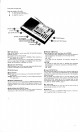
LOCATION AND FUNCTION OF CONTROLS Front pant and right side {earn key marks on the radio » tor scanning or presetting 0 for AM (LW, MW, SW) reception & for BICEPS reception ED POWER Switch £} SLEEP Timer Button ) LIGHT Button -3 Telescopic Antonia 5 SIGNAL STRENGTH indicator [5) EXECUTE Key and Counter Keys FP Frequency Display @ POWER Switch .Set this switch to ON to turn on the radii. To turn off, set it to OFF. # SLEEP Timer Button Press this button to set the seep timer. See page 13.
Front panel and right side Green key marks on the radio e for scanning or presetting il for AM {LW. MW, SW) reception for SEISMIC reception ENTER Kelley) Ls and Lz Keys Scan START/STOP Key {f9) MANUAL TUNING Keys{}) AM ANTENNA B ADJUSTMENT Contort SSH/CW COMPENSATORY W Tone Controls {3} VOLUME Contort @ RF GAIN Selector . Used for AM reception. which means MW, LW and SW (including BICEPS) reception. SW: Suavity set this selector to DX, WILLIAM: Usually set this selector to NORMAL.
Rear and diet side COMPUTER BACK UP * BATTERY Compartment {J Radio Battery Compartment {3 © stand Paige the stand as illustrated for easy use. @ Earphone Jack [P} For private listening with an earphone. When the earphone is plugged in, the speaker is automatically disconnected € Recording Output Jack {£3) For recording radio programs with a tape recorder. Connect this jack to the microphone input jack of the tape recorder with a suitable cord.
DIRECT TUNING it you know the frequency of & station to be received, you can tune in the station easily by Direct Tuning, Refer to “HOW TO INPUT A FREQUENCY™. # The numbers in the illustration refer to the sequence of operation. Sot the POWER Choose tha input the frequency of switch 1o ON. desired band. 9 the station to b received. Ex: 10 Input AM 6,055 kHz [ Crass the Counter Keys In the order 8,0, 5, 5. Then, within 10 seconds, B0 prods the EXECUTE key _J b5 % T055m 5055. ) The station |s tuned in.
HOW TO INPUT A FREQUENCY The frequency range of this radio is: FM 76.00 to 108.00 MHz AM 150 to 29,999 KHz Press the Counter Keys, then press the EXECUTE key. You can now hear the station whose frequency you have just input. Soto: Press the EXECUTE key within 10 seconds after pressing the Counter Keys. {f you do not, tha previous station will come back again. input a frequency beginning at the digit farthest to tha left. Example 1: FM 80.1MHz © Press the Counter Keys in the order 9,0, 1. “90.
MANUAL TUNING Use Manual Tuning when you do not know the Frequency of the station you want 1o tune in, or when you want to tune in a station more precisely tater Scan Tuning ® The numbers in the frustration refer to the sequence of operations. Set the POWER Choose the Crass the increases the frequency) of the < DOWN switch to ON. desired band. 9 key {to decrease). f you keep the key depressed, the frequency changes continuously.
SCAN TUNING Input to the Ls and L2 keys the low and high limits of the Frequency range which includes the stations you most often listen to. Then, use Scan Tuning. # The numbers in the illustration refer to the sequence of operations. Set the POWER 0 Input the low s0d high limits of the desired frequency range. switch input the frequency range of the International SW 31 miter band * —AM 9,500 {0 9,775kHz. 1. Input 9,500KHz to the Ly key, & Pvgsishg %anin{dKGVS in :'he @ @ order and press the o EXECUTE key.
1 Notes on inputting 2 frequency to the L: and {2 keys ® The AM 150KHz frequency is preset at the factory 1o both L and Lz keys. # Once input, the frequency wiki not be canceled unfit another frequency is input. # You can change the frequency input 1o either the Ls ar the Lz key. # if you input AM frequencies to the keys, any previously input FM frequencies will be erased ™, or vice versa. When next scan tuning the FM band, input them again if required. * Neck tne JI indication in the Frequency Display.
Notes ® The AM 150 kHz frequency i is prose to all MEMORY PRESET buttons at the factory. ® Either an FM station or an AM station can be preset to a MEMORY PRESET bunion, for a total of 6 stations. The L and Lz keys can be used as MEMORY PRESET buttons, making it possible to preset 8 stations in all. # if you want to add a new station and all MEMORY PRESET buttons have already been preset, the presetting of one button will have 1o be changed.
EXTERNAL ANTENNA CONNECTION FOR FM RECEPTION in & steel-frame building, & mountainous area, at a distance from the transmitter or in a location where ignition noise is severs, FM reception may be unsatisfactory with the Telescopic Antenna. in this case, cornet a commercially available external FM antenna to the EXT ANT terminals on the right side of the set as illustrated. Use a 75-ohm coaxial cabin for the lead-in.
SPECIFICATIONS Semiconductors Si gnat circuit: 410s, 11 Fests, 23 transistors, 16 diodes Auxiliary circuit: 1 LSI § ICs, 25 transistors, @ diodes (8§ LED included) FM: Superheroes AM: Dual conversion supersaturate FM 76 to 108 MHz AM 150 to 29,999 kHz {2,000 to 10m) Giro system Frequency range Antennas Telescopic antenna (RAMIFY} Built-in fer rite bar antenna (AM 360 to 2,143 kHz} External antenna terminals (AM) Speaker Approx.