SERVICE MANUAL MODEL –––––– COMMANDER –––––––––––– KP-43T70C KP-43T70C KP-53SV70C KP-53SV70C KP-61SV70C KP-61SV70C DVD/ VTR MUTING SAT/ CABLE DEST. CHASSIS NO. ––––– ––––––––––– RM-Y906 Chilean SCC-P19AA RM-Y906 SCC-P19AA Peru RM-Y906 Chilean SCC-P19BA RM-Y906 SCC-P19BA Peru RM-Y906 Chilean SCC-P19CA RM-Y906 SCC-P19CA Peru MODEL –––––– RA-3 CHASSIS COMMANDER –––––––––––– DEST. CHASSIS NO.
KP-43T70C/53SV70C/61SV70C RM-Y906 RM-Y906 RM-Y906 SPECIFICATIONS Projection system 3 picture tubes, 3 lenses, horizontal in-line system Picture tube 7-inch high-brightness monochrome tubes (6.3 raster size), with optical coupling and liquid cooling system Projection lenses High performance, large diameter hybrid lens F1.
KP-43T70C/53SV70C/61SV70C RM-Y906 RM-Y906 RM-Y906 SELF DIAGNOSIS FUNCTION 1. Summary of Self-Diagnosis Function • • This device includes a self-diagnosis function. In case of abnormalities, the TIMER/STANDBY indicator automatically blinks. It is possible to predict the abnormality location • by the number of blinks. The Instruction Manual describes blinking of the TIMER/STANDBY indicator.
KP-43T70C/53SV70C/61SV70C RM-Y906 4. RM-Y906 RM-Y906 Self-diagnosis screen displays • In cases of malfunctions where it is not possible to determine the symptom such as when the power goes off occasionally or when the screen disappears occasionally, there is a screen display on whether the malfunction occurred or not in the past (and whether the detection circuit operated or not) in order to allow confirmation.
KP-43T70C/53SV70C/61SV70C RM-Y906 RM-Y906 RM-Y906 6. Self-diagnosis function operation OCP Low B and +B line detect DET SHORT, and shut-down POWER ON RELAY. Reset by turning power on/off. In case of +B is loaded approx. 1.3A or more, microcomputer detects it via IC651. OVP In case of +B becomes approx. 150V or more, POWER ON RELAY shuts down and microcomputer detects it via IC651. Reset by turning power on/off just the same as OCP.
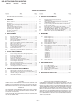
KP-43T70C/53SV70C/61SV70C RM-Y906 RM-Y906 RM-Y906 TABLE OF CONTENTS Section –––––– Title –––– Page –––– SELF DIAGNOSIS FUNCTION ............................................ 4 Remote Control ....................................................................... 7 Precautions .............................................................................. 8 Installing and Connecting the Projection TV .......................... 8 Basic Set Up ..............................................................
SECTION 1 GENERAL The operating instructions mentioned here are partial abstracts from the Operating Instructions Manual. The page numbers of the Operating Instruction Manual remain as in the manual. (Part no : 3-867-647-21) Remote Control POWER* (pages 14, 31, 32) MUTING (page 14) In the instructions that follow, SYSTEM OFF we will refer to the buttons on (page 16) your remote control. Keep this flap unfolded and VCR/DVD/MDP use this page for reference.
Precautions Installing and Connecting the Projection TV (continued) Safety Note on cleaning Installing • Operate the projection TV only on 110220 V AC. • The plug is designed, for safety purposes, to fit into the wall outlet only one way. If you are unable to insert the plug fully into the outlet, contact Sony Authorized Service Center.
Installing and Connecting the Projection TV (continued) CONTROL S cable Connector Types You may find it necessary to use some of the following connector types during set up. Sony cable for CONTROL S connection. This feature is exclusive to Sony products and allow greater control of all Sony equipment. Coaxial cable Push into connection. Standard TV cable and antenna cable Plug Type Push into connection. Screw-on Type Screw into connection.
Installing and Connecting the Projection TV (continued) Disconnect all power sources before making any connections. Connecting a cable TV system/ antenna to a VCR (Rear of projection TV) AUX 1 Attach the coaxial cable from the TO CONVERTER incoming cable connection or antenna to VHF/UHF IN on the VCR.
Installing and Connecting the Projection TV (continued) Disconnect all power sources before making any connections. Connecting two VCRs for tape editing (Rear of projection TV) By connecting a second VCR to MONITOR OUT, you can record a program being played by the primary VCR to the second VCR or perform tape editing and dubbing. AUX TO CONVERTER 1 Connect the VCR intended for playback using the connection instructions on page 6 of this manual.
Installing and Connecting the Projection TV (continued) Disconnect all power sources before making any connections. Connecting an audio system (Upper illustration) (Rear of projection TV) For more dynamic sound, connect an audio system to the projection TV. 1 Using an AUDIO cable, connect AUDIO (VAR/FIX) OUT on the projection TV to one of the unused Line inputs (e.g. Tape-2, AUX1, etc.) on the stereo.
Basic Set Up (continued) 2 Press POWER on the projection TV. The TIMER/STANDBY indicator lights in green. Right side MAIN POWER KP-43T70A/ 53SV70A only POWER MAIN POWER For KP-43T70C/53SV70C/61SV70C only Press POWER on the projector TV.
Using Your New Projection TV (continued) Watching the TV Many TV features can be accessed directly through the remote control. The following chart will explain the function of some buttons found on your remote control. Using the White Labeled Buttons for Projection TV Operations MAIN POWER (on the right side of the projection TV) Switches the projection TV on and off. TV (FUNCTION) Activates the remote control for use with the projection TV. TV POWER Turns the projection TV on and off.
Using Your New Projection TV (continued) Using the White Labeled Buttons for Projection TV Operations CC Press repeatedly to scroll through available displays: XDS (Extended Data Service) Displays a network name, program name, program type, program length, program description, call letters and time of the show if the broadcaster offers this service. Caption Vision Displayed on the screen if the broadcaster offers this service.
Using Your New Projection TV (continued) REFER TO THE ILLUSTRATION OF THE REMOTE CONTROL ON THE INSIDE FRONT COVER OF THIS MANUAL AS YOU REVIEW THIS CHART Using the Yellow Labeled Buttons for PIP Operations CH 0 - 9 or Press to select the TV channel on which the symbol “b” is displayed. (for details, see “Watching the TV” on page 14) Speed Surf 1 Press and hold CH + or – to change the channel number rapidly. 2 Release to display the desired channel.
Adjusting Your SET UP (menus) (continued) Using the Video Menu Video Modo: Vívido Ajuste de imagen Trinitone: Alto You can choose one of five different video modes that best suits the program you are watching. You can also perform the “Ajuste de imagen” (such as “Brillo,” “Color,” etc.) for “Películas,” “Personal 1” or “Personal 2” to suit your taste. Vívido: Select for enhanced picture contrast and sharpness. Estándar: Select to display a standard picture for normal viewing environments.
Adjusting Your SET UP (menus) (continued) Sí: Select to listen to the sound from the projection TV speakers alone. No: Select to turn off the projection TV speakers and listen to the projection TV’s sound only through an external audio system’s speakers. SAVA SP: Select to turn off the projection TV speakers and listen to the projection TV’s sound only through the Sony SAVA series speaker system. You can adjust volume, muting, “Modo surround,” and “Modo superwoofer” with the projection TV’s remote control.
Adjusting Your SET UP (menus) (continued) Using the Ajustes de canal Menu ch Ajuste de canal Nombre del canal Canal favorito :Auto Canal omitir/agregar Auto programación Cable: Sí ch Mover Seleccionar Salir To select the Ajustes de canal menu: / Highlight ch Easy recognition of the channel you are watching MENU For detailed information on using the remote control to modify menu settings, refer to “Learning Menu Selection” on page 19.
Adjusting Your SET UP (menus) (continued) Setting and Selecting Canal favorito The Canal favorito feature of your projection TV enables easy access to the eight channels that you preset (or the last channel that you were watching). Your Canal favorito options can be set automatically or manually. The factory setting for “Canal favorito” is “Auto.” When “Canal favorito” is set to “Auto,” the last eight channels selected with the 0–9 buttons will be set as Canal favorito options.
Adjusting Your SET UP (menus) (continued) Using the Ajustes Menu Ajustes Caption Vision: CC1 Lenguaje: Español Etiqueta de video Flash Focus: No Sistema de color ch Mover Seleccionar Ajustes Some programs are broadcast with Caption Vision. Caption Vision: C C 1 CC2 Lenguaje: To display “Caption Vision,” select CC 1, CC 2, E t i q u e t a d e v i d eCo C 3 CC Flash Focus: N 4o CC 3, CC 4, TEXT1, TEXT2, TEXT3 or TEXT4 from S i s t e m a d e c o l To er x t 1 Text2 T e x t3 the menu.
OperatingYour Video Equipment Adjusting SET UP (menus) (continued) VCR manufacturer code numbers Setting the Manufacturer's Code Manufacturer You can use the supplied remote control to operate Sony or non-Sony video equipment that has an infrared sensor. Press CODE SET, DVD/VTR (FUNCTION), and the 0-9 buttons to enter the manufacturer’s code number (see the following chart), then press ENTER.
Adjusting SETBox UP (menus) (continued) OperatingYour a Cable Setting the Manufacturer's Code You can program the supplied remote control to operate a cable box. Press CODE SET, SAT/CABLE (FUNCTION)*, and the 0-9 buttons to enter the manufacturer’s code number (see the following chart), then press ENTER. For example, to operate a Pioneer cable box: CODE SET FUNCTION SAT/CABLE ENTER 2 1 4 Manufacturer code numbers (cable box) Code Manufacturer Hamlin/Regal Jerrold/G.
Troubleshooting (continued) Cannot receive upper channels (UHF) when using an antenna • Make sure “Cable” is “No” in the Ajuste de canal menu. (see “Cable” on page 25) • Use “Auto programación” to add receivable channels that are not presently in the TV’s memory. (see “Auto programación” on page 25) No color • • • • Adjust “Color” in the Video menu. (see “Ajuste de imagen” on page 20) Black and white programs cannot be seen in color.
KP-43T70C/53SV70C/61SV70C RM-Y906 RM-Y906 RM-Y906 SECTION 2 DISASSEMBLY 2-1. REAR BOARD REMOVAL 2-3. SERVICE POSITION 1 Disconnect CN203 on A board. From CG board CN1304. (The extension cable is not supplied because of the A board countermeasure for radiation.) CN203 G board 2 Covers Cut them off with a plier or the like from chassis assembly in case of checking printed circuit boards. After checking, turn over the covers and secure them with screws.
KP-43T70C/53SV70C/61SV70C RM-Y906 RM-Y906 RM-Y906 2-5. HA BOARD AND HB BOARD REMOVAL (KP-43T70C) 2-7.
KP-43T70C/53SV70C/61SV70C RM-Y906 2-9. A, G BOARD AND FA BOARDS REMOVAL 4 Eight screws (+BVTP 3x12) 7 Two screws (+BVTP 3x12) RM-Y906 2-11. HIGH-VOLTAGE CABLE INSTALLATION AND REMOVAL 3 Terminal board (1) Remover 1 Rubber cap 9 A board 2 HV cable turn 90° 8 Claw 2 Seven screws (+BVTP 3x12) 6 G board (2) Installation 1 Two screws (Screws (4x20), tapping) 1 HV cable Hook Main bracket 2-10.
KP-43T70C/53SV70C/61SV70C RM-Y906 RM-Y906 RM-Y906 SECTION 3 SET-UP ADJUSTMENTS 3-1. SCREEN VOLTAGE ADJUSTMENT (ROUGH ALIGNMENT) 10. Set VPNT 28 RON to “000”, 29 GON to “000” and 30 BON to “001” to show only the blue color. 1. Receive the Monoscope signal. 2. Set 50% BRIGHTNESS and minimum PICTURE. 11. Adjust blue CRT lens just the same as green. 3.
KP-43T70C/53SV70C/61SV70C RM-Y906 RM-Y906 RM-Y906 3-5. DEFLECTION YOKE TILT ADJUSTMENT 3-7. 4-POLE MAGNET ADJUSTMENT 1. Receive the Monoscope signal. 2. Set in service mode. 1. Receive the Dot signal. 2. Set in service mode. 3. Set VPNT 29 GON to “001” 28 RON to “000” and 30 BON to “000” to show only the green color. 3. Set VPNT 29 GON to “001” 28 RON to “000” and 30 BON to “000” to show only the green color. 4.
KP-43T70C/53SV70C/61SV70C RM-Y906 RM-Y906 RM-Y906 3-9. ELECTRICAL ADJUSTMENT BY REMOTE COMMANDER 2. MEMORY WRITE CONFIRMATION METHOD 1. After adjustment, remove the plug from AC outlet, and then By using Remote Commander (RM-Y906),all circuit adjustments replace the plug in AC outlet again. 2. Turn the power switch ON and set to Service Mode. can be made. NOTE : Test Equipment Required. 3. Call the adjusted items again and confirm they were adjusted. 1. Pattern Generator 2. Frequency counter 3.
0 1 2 3 4 5 6 7 8 9 10 11 12 13 14 15 16 17 18 19 20 21 22 23 24 25 26 27 28 29 30 31 32 33 34 35 36 VPOS VSIZ VCOM VLIN VSCO HPOS HSIZ PAMP UPIN LPIN PPHA AFC VBOW VANG REF RDRV BDRV RCUT BCUT SCON SHUE SCOL CDM2 DPIX NOTC CROM TOT SHPF RON GON BON DCOL CDMD LBLK RBLK PREC PREY 0-63 0-63 0-3 0-15 0-15 0-15 0-63 0-63 0-15 0-15 0-15 0-3 0-15 0-15 0-3 0-63 0-63 0-15 0-15 0-15 0-15 0-15 0,1 0,1 0,1 0-15 0,1 0-3 0,1 0,1 0,1 0,1 0,1 0-15 0-15 0-3 0-3 ITEM ADJUSTMENT DATA NUMBER ITEM RANGE VPNT : Fixed data
– 32 – 0 31 25 25 0 62 0 194 62 225 -80 -15 0 32 238 23 27 X(*1) X(*1) X(*1) X(*1) X(*1) X(*1) X(*1) X(*1) X(*1) X(*1) X(*1) X(*1) 0 144 1 102 212 1 000 / 000 000 / 000 -70/-190 xxxx / xxxx xxxx / xxxx xxxx / 271 000 / 000 080 / -130 -20 / -226 -187 / xxxx xxxx / -115 xxxx / 198 000 / 000 080 / -130 -61 / -206 195 / xxxx xxxx / 124 xxxx / 247 RED H SKEW OFFSET DATA OF AUTO REGI BLUE H SKEW OFFSET DATA OF AUTO REGI AUTO REGI ERROR CODE TIMING TO GET A/D DATA OF AUTO REGI AUTO REGI PATTERN UPPER V POSITION A
RBAS RTRE BBEH BBEL SUFE 0-63 0-63 0-15 0-11 7 – 33 – TRUSURROUND EFFECT (L+R) COARSE TRUSURROUND EFFECT (L+R) FINE TRUSURROUND EFFECT (L-R) COARSE TRUSURROUND EFFECT (L-R) FINE TRUSURROUND EFFECT ( C ) COARSE TRUSURROUND EFFECT (C) FINE TRUSURROUND EFFECT ( S ) COARSE TRUSURROUND EFFECT ( S) FINE TRUSURROUND EFFECT ( S ) COARSE TRUSURROUND EFFECT ( S) FINE TRUSURROUND EFFECT (L,R) COARSE TRUSURROUND EFFECT (L,R) FINE SRS SPACE LEVEL COARSE SRS SPACE LEVEL FINE SRS CENTER LEVEL COARSE SRS CENTER LEVEL FI
0-63 0-63 – 34 – 0-255 0-127 0-63 0-7 0-15 0-31 0-31 0-15 0-15 0-15 0-15 0,1 0,1 0-3 0,1 AREA SERS VCHP 0-3 0-3 0-3 CCHP CCHN 0 1 2 3 DISP FWl FW2 IDXT ITEM ADJUSTMENT NUMBER ITEM OP 0 1 0-63 0-7 0-7 DATA RANGE 0-63 0-63 ITEM ADJUSTMENT DATA NUMBER ITEM RANGE CCD 0 1 2 ITEM ADJUSTMENT DATA NUMBER ITEM RANGE ID PIPH PIPV PYSD PYDL PHDL PMVD PIVD PCON FRMY IPER IPEB PCPS PCPF PPLL PVNR 9 2 3 2 STANDARD DATA 39 29 STANDARD DATA 0 1 0 STANDARD DATA 84 21 1 0 1 26 22 7 7 0 0 0 0 0 0 ST
KP-43T70C/53SV70C/61SV70C RM-Y906 DISPLAY DVD/ VTR MUTING SAT/ CABLE Data up (Rough adjustment) PJED mode Color change GRNnBLUnRED TV TV/VTR FREEZE TV SWAP m PIP N M POSITION AUDIO X z Adjustment item up CC TV/VIDEO ANT 1 2 3 4 5 6 7 8 9 Data down (Rough adjustment) PJED mode Test signal crosshach+video signal dots+video signal crosshach+black dots+black off ENTER 0 INDEX GUIDE RESET MENU Category down VOL CH CODE SET ( " PJED " data up/down GRN CENT (H) 000 (V) 000
KP-43T70C/53SV70C/61SV70C RM-Y906 RM-Y906 RM-Y906 1. Press 9 key on the remote commander to shift to the fine [GREEN REGISTRATION ADJUSTMENT] adjustment mode. The green marker (in the GRN mode) appears on the center of 1. Select GRN CENT with the 1and 4 keys on the remote commander. 2. Adjust the crosshatch line goes straight vertically and horizontally with the joystick on the remote commander. GRN CENT 000 the screen. 2.
KP-43T70C/53SV70C/61SV70C RM-Y906 [RED REGISTRATION ADJUSTMENT] RM-Y906 RM-Y906 2. Use the 1 and 4 keys or the joystick on the remote commander, move the marker everywhere you want to adjust and 1. Change to VPNT mode and set VPNT 28 RON to “001”, 29 GON to “001” and 30 BON to “000” to show the green and [BLUE REGISTRATION ADJUSTMENT] red colors. 2. Change the VPNT mode to the PJE mode. 1. Change to VPNT mode and set VPNT 28 RON to “001”, 29 3.
KP-43T70C/53SV70C/61SV70C RM-Y906 RM-Y906 RM-Y906 3-11. AUTO REGISTRATION ERROR CODE LIST [ERROR CODE LIST] ERROR CODE DISCRIPTION 00 No Error 10 Sensor Output Level Low NOTE * Check wiring, beam position, sensor. 0 : Upper Center 1 : Middle Left 2 : Middle Right 3 : Lower Center 20 Sensor Output Level High * Check OP-amp circuit.
KP-43T70C/53SV70C/61SV70C RM-Y906 RM-Y906 RM-Y906 SECTION 4 SAFETY RELATED ADJUSTMENTS [ G BOARD] 4-1. HV REGULATION CIRCUIT CHECK AND ADJUSTMENT 4-2. HV HOLD DOWN CIRCUIT OPERATION CHECK AND ADJUSTMENT When replacing the following components marked with on the schematic diagram always check HV regulation, and if necessary re-adjust. : : When replacing the following components marked with on the schematic diagram always check hold-down voltage and if necessary re-adjust.
KP-43T70C/53SV70C/61SV70C RM-Y906 RM-Y906 RM-Y906 4-4. +B OVP CONFIRMATION 1. 2. 3. 4. Connect an external dc power supply to TP OVP. Supply 120VAC to variable autotransformer. Set PICTURE and the BRIGHTNESS controls to minimum. Gradually turn the external dc power supply, and check if OVP works properly when the voltage of the external dc power supply is between 139.0 ~ 155.0V.
KP-43T70C/53SV70C/61SV70C RM-Y906 RM-Y906 RM-Y906 SECTION 5 CIRCUIT ADJUSTMENTS 5-1. TV INPUT SUB CONTRAST ADJUSTMENT (VPNT-SCON) 5-3. COMPONENT INPUT SUB-HUE AND SUB-COLOR ADJUSTMENT (DAC-UVSH, UVSC) 1. Receive the color-bar signal. 2. Mode : Personal 1 or 2. PICTURE : maximum COLOR : minimum BRIGHTNESS : center TRINITONE : medium ABL : CN801 pin 4open SERVICE DATA VPNT SCON : 7 3. Set to service mode. 4. Connect an oscilloscope between pin 7 of CN204 (A board) and ground. 5.
KP-43T70C/53SV70C/61SV70C RM-Y906 RM-Y906 RM-Y906 5-5. SUB-HUE , SUB-COLOR AND MAIN CONTRAST ADJUSTMENT (MC-MYDR, MSHU, MSCL, SC-SSHU, SSCL) 5-7. PIP POSITION ADJUSTMENT (PI-PIPH, PIPV) 1. Receive the color-bar signal. 2. Mode : Personal 1 or 2. PICTURE : maximum COLOR : center BRIGHTNESS : center TRINITONE : medium SERVICE DATA MC-MYDR : 22 SERVICE DATA MC-MSHU : 31 SERVICE DATA MC-MSCL : 31 SERVICE DATA SC-SSHU : 31 SERVICE DATA SC-SSCL : 31 3. Set to service mode and set to P & P model . 4.
SECTION 6 DIAGRAMS 6-1.
BLOCK DIAGRAM (2) BUFFER Q152 DET OUT 2 63 MTV V MAIN V OUT 41 VIDEO BUFFER Q1103,1104 BUFFER Q1701 BUFFER Q1702,1703 FL1701 H.SEP Q004 DET OUT SWITCH Q151 RF AGC SDA SCL RF AGC BUFFER Q153 H.
Q232 Q229 IC206 YCJ 19 TVIN 23 DVD Y TVOUT 12 BUFFER Q228 PEEKING Q262,227 INV Q1912 1 3 BUFFER Q305,306 +9V 64 CIN IC301 YUV SWITCH IC1901 YVU CONTROLLER BUFFER Q220 BUFFER Q219 BUFFER Q218 ROUT 20 7 63 YIN 2 GRAY GOUT 24 BOUT 26 TO A BOARD SYSTEM CONTROL BLOCK IKIN 27 BUFFER Q231 BUFFER Q230 SBLK IC1905 PIP PROCESSOR M.VSYNC SEL BUFFER Q1918 28 YIN 30 UIN 32 VIN 1 X1903 20.48MHz 3 XIN 4 XQ SDA 21 SDA SCL 22 SCL Y OUT 8 U OUT 9 V OUT 7 S.VSYNC 19 S.HSYNC M.
BLOCK DIAGRAM (3) LEFT IC804 PEAK HOLD 5 7 Q804 6 IC806 BUFF 6 7 18 17 16 15 57 IC802 IV CONV CN3001 1 SENSOR 3 CN802 LEFT 1 2 5 UPPER UPPER 3 1 3 1 Q803 2 3 1 10 SENSOR LOWER 5 RIGHT 7 13 14 12 SW Q801 14 Q802 13 RIGHT 9 CN3001 9 +5V D+5V FINB 5 30 SCL SDA 50 48 MAIN SCL MAIN SDA 8 6 BINT 8 Q805 12 1 10 L IC808 (1/6, 3/6) I HP I DREG OVF I DREG BSY I DREG ACK 7 26 27 28 I VP 8 6 DREG SCL O DREG SDA I DREG SDA O IIC SW 49 47 46 58 1 17 8 11 12 29 18
5-1.
BLOCK DIAGRAM (5) POWER SUPPLY ( ) G H/V OUT V DRIVE (+) IC1502 SUB DY-DRIVE CN651 RH RV GH TO A BOARD CN402 10 15 9 14 MUTE Q1508 M 18 1 CN1503 HR OUT 16 4 HR RET 11 2 VR OUT 13 3 VR RET 9 1 HG OUT 7 4 HG RET 6 7 3 IC1506 SUB DY-DRIVE GV BH BV 5 15 3 14 1 6 MUTE Q1501 J N 6 V DRIVE (-) TO A BOARD CN202 5 VP 13 14 12 7 6 8 IC1509 V OUT DY (B) 7 1 5 3 V-SEP Q1505 4 CN1504 18 2 VG OUT 16 3 VG RET 11 1 HB OUT 13 4 HB RET 2 9 RELAY G V
6-2. FRAME SCHEMATIC DIAGRAM S S S CN1291 3P WHT-L :S-MICRO TO HA:CN1201 S ST BY 5V S3001 HC SIRCS E TO G:CN506 TO G:CN1503 TO G:CN1506 6-3. CIRCUIT BOARDS LOCATION E CN735 9P RED :S-MICRO CN732 4P WHT :S-MICRO TO CR:CN701 CN1301 3P WHT :S-MICRO TO DY(R) H(-) ANT SW 2 E CN1304 6P WHT :S-MICRO TO A:CN203 TO CR:CN702 ANT SW 1 NC 9V 200V R R + + - - L E R L E E FR C IN E FRONT SW E FR Y IN E FR V IN FR L IN E FR R IN B CLK B DAT E B INT B LEFT B/S VM.RET VM.
1 3 2 4 5 6 7 8 10 9 11 12 13 15 14 16 17 18 19 20 22 21 23 24 • A (1/3) BOARD WAVEFORMS 2 L155 47µH :LAV35 R163 39k :CHIP C176 0.0022 B:CHIP +9V SAP Q1108 DTC143TKA MUTE Q1111 2SB709A SIRCS MIX. R1140 4.7k :CHIP S-OUT D1125 1SS355TE-17 IR MUTE2 RM-IN 0.6 C015 220p CH:CHIP :CHIP 68k R1137 10k :CHIP 5.1 C016 0.047 25V B:CHIP R037 2.2k :CHIP R1164 BCLK GND BDAT R E B E G E 0.8 R044 1M :CHIP R046 10k :CHIP R084 100 :CHIP C442 :PT 0.033 0.
C821 47 25V TEST16 TEST5 TEST17 TEST4 2.4 BCLK TEST21 YSOUT TEST22 YMOUT TEST23 BOUT 0 0 R872 100 :CHIP DGND D-RV 2.1 1.7 2.1 2.4 2.4 2.4 0.1 R842 100 :CHIP 1.9 :CHIP 4.8 R839 100 :CHIP 4.8 I DPJE SVA2 O AREG SW I DREG ACK IC805 CXP86324-021Q PJED-CPU 2 C936 0.0047 B:CHIP C954 0.0068 B:CHIP RREF LREF LOUT AVDD LRCK AGND ROUT AGND AVDD -0.2 1.1 -0.2 1.1 -0.2 C960 0.1 25V F:CHIP R915 1k :CHIP 1.6 2.1 RREF LREF LOUT AVDD C930 0.
+9V Y R1937 10k :CHIP +5V 0.1 1 SMS 1.7 9V 1.5 H LOCK RESET +5V +9V 7 D6H R1930 0 :CHIP 0.4 EU EV EY DU FB1902 Y +5V BLM601 SCL +5V SDA C329 22 25V EY EY EU EU R340 470 :CHIP EV EV C328 0.01 B:CHIP Y 3.4 Q226 2SD601A PEEKING1 R335 470 :CHIP R320 10k :CHIP SBLK SBLK R336 R337 1k 1k :CHIP :CHIP R338 15k :CHIP C330 22 25V 5.9 4.6 25V B:CHIP C1902 0.1 25V B:CHIP C1903 0.1 25V B:CHIP R1905 4.7k :CHIP 1.4 VDDA1 2.3 YIN VDD C1953 0.01 B:CHIP C1972 0.
A BOARD ] A (2/3) [PJED, REGI-CORRECTION ] 3 D408 K-7 3 D820 J-1 3 D1118 3 Q002 D003 B-1 3 D409 M-3 - D821 J-2 3 D1119 G-9 3 Q003 D004 F-1 3 D412 M-8 3 D822 J-1 3 D1120 F-9 3 B-10 3 D413 M-7 3 D823 J-2 3 D1121 F-9 M-8 J-2 Q1903 D-7 2 Q1904 * Q022 F-2 2 Q232 E-3 2 Q808 H-9 1 Q1117 F-9 2 Q1905 D-7 2 Q023 F-2 2 Q301 D-3 2 Q809 H-9 1 Q1118 H-9 2 Q1906 C-10 1 Q024 B-4 2 Q302 D-3 2 Q811 H-2 2 Q1119 G-9 2 A-9 2 Q151 B-5 1 Q303
IC1506 STK392-150 SUB DY-DRIVE IC1502 STK392-150 SUB DY-DRIVE R1528 3.3k :RN R1525 3.3k :RN R1523 2.2 1/2W :RN R1527 220 2.2 R1526 220 R1554 15k :RN R1519 47k R1535 1k :RN R1536 3.3k :RN C1536 100p :B C1551 0.0022 :B C1508 0.0022 :B R1550 12k :RN L1512 47µH :LHL08 R1518 10k Q1501 2SC3311A MUTE D1522 MTZJ-24 C1540 470 25V R1559 10 1W :RS R1515 220 D1525 GP08D PUMP UP L1513 10µH :LHL08 L1501 47µH :LHL08 Q1505 2SC3311A V-SEP C1525 47p :CH R1583 100 15.6 -0.
G [ ] H/V, DY DRIVE, POWER SUPPLY – G Board – G BOARD DIODE D1503 B-15 D1504 G-15 D501 E-13 D1505 G-13 D505 E-13 D1506 G-13 D506 E-11 D1507 F-14 D507 E-11 D1509 G-12 D513 E-13 D1510 F-13 D517 C-9 D1513 I-11 D518 D-8 D1515 I-12 D520 D-10 D1520 J-12 D522 D-3 D1521 J-13 D525 F-8 D1522 I-15 D526 F-8 D1523 H-14 D528 B-4 D1525 I-15 D529 D-6 D530 E-12 D531 F-13 Q501 D532 B-4 Q502 B-8 D533 B-6 Q503 D-11 D534 D-5 Q505 F-11 D601 G-3 Q506 F
G1 G2 G4 5 1,2 V902 PICTURE TUBE 6 7 G3 4 G4 G1 G2 6 H 7 G5 CG 1,2 5 4 H G1 G2 G4 1,2 5 4 K10 G5 G3 6 H 7 V901 PICTURE TUBE G5 G3 [G DRIVE, VM DRIVE] CR [ R DRIVE ] CB V903 PICTURE TUBE K10 K10 – CG Board – HV.BLOCK HV.BLOCK HV.BLOCK BRACKET CRT CRT CG (G DRIVE,VM DRIVE) TO FOCUS BLOCK CN737 TO FOCUS BLOCK B-H(+) DY(B) NC H+ NC H(MID) DY(H) 4P :VH TO G BOARD CN504 B-H(-) H- G2 R734 100 1/2W CN740 HB.IN V.IN VB.IN SUB DY VB.RET V.RET H.RET HB.
1 3 2 4 5 A 6 CN1203 7P WHT-L :S-MICRO TO A(1/3) BOARD CN002 4-10P STBY 5V R1206 220 E KEY POWER TIMER LED MENU KEY B R1201 15k S1201 FLASH FOCUS C R1202 4.7k D1201 SLR-325VCT31 R1205 2.2k S1203 TV/VIDEO S1204 + S1205 - S1206 + S1207 POWER CHANNEL MENU KEY E D1293 MTZJ-5.6 PROT D1291 GP1U28Y IR SENCER STBY 5V C1291 10 16V SIRCS E R1291 100 D1292 MTZJ-5.
1 3 2 4 5 6 CN1253 11P WHT-L :S-MICRO A TO U BOARD CN1702 C1255 22 25V J1251 S VIDEO R1255 4.7k E FR C-OUT C1254 22 25V FRONT SW D1251 MTZJ-10 PROT R1260 75 R1256 75 D1256 MTZJ-10 PROT D1252 MTZJ-10 PROT VIDEO 1 INPUT L(MONO) C1253 22 25V R1259 75 D1255 MTZJ-10 PROT FR Y-OUT FR V-OUT E FR L-OUT 2 1 AUD IO E R1258 470k C1252 22 25V D1254 MTZJ-10 PROT R1257 470k C1251 22 25V D1253 MTZJ-10 PROT 2 3 1 R E E 2 VIDEO2 B 7 C R1251 10k R1253 2.2k R1252 3.
1 3 2 4 5 6 7 A JW6002 JW(7.5MM) JW6004 JW(7.5MM) B JW6001 JW(7.5MM) JW6003 JW(7.5MM) L6001 LF CN6002 2P WHT :VH R6002 4.7M 1/2W 110~220V 50/60Hz C6002 0.22 300V C6004 0.47 R6005 0.82 20W VD6001 470 C R6003 0.82 20W CN6003 :FASTON F6001 6.3A 250V R6001 8.
KP-43T70C/53SV70C/61SV70C RM-Y906 RM-Y906 RM-Y906 6-5.
KP-43T70C/53SV70C/61SV70C RM-Y906 2SK2663 1SS133-T-77 D3S6M-F ERA22-08 ERC04-06SE ERC06-15S D4SB60L-F + + CATHODE G D ~ ~– ~ ~ – SLR-325VCT31 S ANODE 2SC3271F-N LETTER SIDE E 1SS355TE-17 UDZ-TE17-10B UDZ-TE-17-22B UDZ-TE17-33B UDZS-TE17-10B UDZS-TE17-5.6B UDZS-TE17-8.2B ANODE CATHODE C B ANODE 11ES2 D1N20R D2L20U MTZJ-10B MTZJ-13 MTZJ-15B MTZJ-2.7A MTZJ-3.9B MTZJ-4.7C MTZJ-5.1B MTZJ-7.5B MTZJ-T-77-4.
KP-43T70C/53SV70C/61SV70C RM-Y906 RM-Y906 RM-Y906 SECTION 7 EXPLODED VIEWS NOTE: • Items with no part number and no description are not stocked because they are seldom required for routine service • The construction parts of an assembled part are indicated with a collation number in the remark column. 7-1. • Items marked " * " are not stocked since they are seldom required for routine service. Some delay should be anticipated when ordering these items.
KP-43T70C/53SV70C/61SV70C RM-Y906 7-2. 62 COVER (EXCEPT KP-43T70C) r : +BVTP 3X12 p : +BVTP 4X12 4 : +BVTP 4X12 ¢ : +BVTP 4X16 RM-Y906 7-685-648-79 7-685-661-14 7-685-661-79 7-685-661-79 63 59 56 56 52 53 78 54 58 55 61 78 60 56 56 51 64 55 63 77 73 63 KP-61SV70C 76 72 63 75 65 71 74 63 70 63 68 67 63 66 63 KP-53SV70C REF. NO. ––––––––– PART NO.
KP-43T70C/53SV70C/61SV70C RM-Y906 7-3. RM-Y906 RM-Y906 The components identified by shading and mark ! are critical for safety. Replace only with part number specified. CHASSIS (KP-43T70C) r : +BVTP 3X12 7-685-648-79 110 109 108 111 107 102 105 102 102 104 106 112 114 152 113 115 102 101 103 102 101 REF. NO. ––––––––– PART NO. –––––––– 101 1-529-396-11 102 4-378-522-31 103 ! 1-223-925-11 104 105 106 107 DESCRIPTION REMARK NO. ––––––––– PART NO.
KP-43T70C/53SV70C/61SV70C RM-Y906 RM-Y906 The components identified by shading and mark ! are critical for safety. Replace only with part number specified. 7-4. 160 CHASSIS (EXCEPT KP-43T70C) 159 r : +BVTP 3X12 7-685-648-79 161 158 154 157 156 153 155 153 162 154 163 164 153 153 165 152 153 151 152 153 REF. NO. ––––––––– PART NO. –––––––– 151 DESCRIPTION ––––––––––––– 152 153 154 1-529-401-11 SPEAKER (13cm) (53SV70C) 1-529-402-11 SPEAKER (16cm) (61SV70C) 1-529-403-11 SPEAKER (6.
KP-43T70C/53SV70C/61SV70C RM-Y906 RM-Y906 RM-Y906 The components identified by shading and mark ! are critical for safety. Replace only with part number specified. 7-5. PICTURE TUBE r : +BVTP 3X12 7-685-648-79 201 220 220 201 220 203 206 KP-43T70C KP-61SV70C 204 206 207 220 205 208 213 220 220 206 214 207 KP-43T70C 219 209 210 EXCEPT KP-43T70C 211 212 220 KP-61SV70C 218 217 215 REF. NO. ––––––––– PART NO.
KP-43T70C/53SV70C/61SV70C RM-Y906 SECTION 8 RM-Y906 FA A ELECTRICAL PARTS LIST The components identified by shading and mark ! are critial for safety. Replace only with part number specified. • The components identified by in this manual have been carefully factory-selected for each set in order to satisfy regulations regarding X-ray radiation. Should replacement be required, replace only with the value originally used. When indicating parts by reference number, please include the board name.
KP-43T70C/53SV70C/61SV70C RM-Y906 RM-Y906 RM-Y906 A REF. NO. ––––––––– PART NO. –––––––– DESCRIPTION ––––––––––––– REMARK NO. ––––––––– PART NO. ––––––––– REF. –––––––– C103 C104 C105 1-163-239-11 CERAMIC CHIP 1-163-227-11 CERAMIC CHIP 1-163-227-11 CERAMIC CHIP 33pF 10pF 10pF 5% 50V 0.5pF 50V 0.5pF 50V C106 C107 C126 C128 C151 1-163-227-11 1-128-551-11 1-128-551-11 1-128-551-11 1-126-935-11 CERAMIC CHIP ELECT ELECT ELECT ELECT 10pF 22µF 22µF 22µF 470µF 0.
KP-43T70C/53SV70C/61SV70C RM-Y906 RM-Y906 RM-Y906 A REF. NO. ––––––––– PART NO. –––––––– DESCRIPTION ––––––––––––– REMARK NO. ––––––––– PART NO. ––––––––– REF. –––––––– C463 1-126-961-11 ELECT 2.2µF 20% 50V C464 C465 C466 C467 C468 1-126-933-11 1-128-551-11 1-128-551-11 1-104-664-11 1-126-963-11 ELECT ELECT ELECT ELECT ELECT 100µF 22µF 22µF 47µF 4.
KP-43T70C/53SV70C/61SV70C RM-Y906 RM-Y906 RM-Y906 A REF. NO. ––––––––– PART NO. –––––––– DESCRIPTION ––––––––––––– REMARK NO. ––––––––– PART NO. ––––––––– REF. –––––––– C908 C909 C910 C911 1-163-222-11 1-163-222-11 1-163-222-11 1-164-690-91 CERAMIC CHIP CERAMIC CHIP CERAMIC CHIP CERAMIC CHIP 5pF 5pF 5pF 0.0022µF 0.25pF50V 0.25pF50V 0.
KP-43T70C/53SV70C/61SV70C RM-Y906 RM-Y906 RM-Y906 A REF. NO. ––––––––– PART NO. –––––––– DESCRIPTION ––––––––––––– REMARK NO. ––––––––– PART NO. ––––––––– REF. –––––––– C1714 C1715 1-163-021-91 CERAMIC CHIP 1-163-021-91 CERAMIC CHIP 0.01µF 0.01µF 10% 10% 50V 50V C1716 C1717 C1718 C1719 C1720 1-163-021-91 1-163-021-91 1-163-021-91 1-163-231-11 1-163-021-91 CERAMIC CHIP CERAMIC CHIP CERAMIC CHIP CERAMIC CHIP CERAMIC CHIP 0.01µF 0.01µF 0.01µF 15pF 0.
KP-43T70C/53SV70C/61SV70C RM-Y906 RM-Y906 RM-Y906 A REF. NO. ––––––––– PART NO. –––––––– DESCRIPTION ––––––––––––– D001 D002 D003 D004 D005 8-719-988-61 8-719-988-61 8-719-988-61 8-719-069-55 8-719-988-61 DIODE DIODE DIODE DIODE DIODE 1SS355TE-17 1SS355TE-17 1SS355TE-17 UDZS-TE17-5.6B 1SS355TE-17 D006 D007 D008 D151 D202 8-719-069-55 8-719-069-55 8-719-069-55 8-719-977-81 8-719-977-28 DIODE DIODE DIODE DIODE DIODE UDZS-TE17-5.6B UDZS-TE17-5.6B UDZS-TE17-5.
KP-43T70C/53SV70C/61SV70C RM-Y906 RM-Y906 RM-Y906 A REF. NO. ––––––––– PART NO. –––––––– FL1702 FL1703 DESCRIPTION ––––––––––––– REMARK NO. ––––––––– PART NO. ––––––––– REF.
KP-43T70C/53SV70C/61SV70C RM-Y906 RM-Y906 RM-Y906 A REF. NO. ––––––––– PART NO. –––––––– DESCRIPTION ––––––––––––– REMARK NO. ––––––––– PART NO. ––––––––– REF.
KP-43T70C/53SV70C/61SV70C RM-Y906 RM-Y906 RM-Y906 A REF. NO. ––––––––– PART NO. –––––––– DESCRIPTION ––––––––––––– REMARK NO. ––––––––– PART NO. ––––––––– REF. –––––––– R060 R061 R062 R063 R064 1-216-049-91 1-216-041-00 1-216-065-91 1-216-065-91 1-216-065-91 RES,CHIP RES,CHIP RES,CHIP RES,CHIP RES,CHIP 1K 470 4.7K 4.7K 4.
KP-43T70C/53SV70C/61SV70C RM-Y906 RM-Y906 RM-Y906 A REF. NO. ––––––––– PART NO. –––––––– DESCRIPTION ––––––––––––– REMARK NO. ––––––––– PART NO. ––––––––– REF. –––––––– R128 R129 R130 1-216-025-91 RES,CHIP 1-216-073-00 RES,CHIP 1-216-057-00 RES,CHIP 100 10K 2.
KP-43T70C/53SV70C/61SV70C RM-Y906 RM-Y906 RM-Y906 A REF. NO. ––––––––– PART NO. –––––––– DESCRIPTION ––––––––––––– REMARK NO. ––––––––– PART NO. ––––––––– REF. –––––––– R356 1-216-063-91 RES,CHIP 3.9K 5% 1/10W R357 R360 R361 R362 R363 1-216-049-91 1-216-051-00 1-208-803-11 1-208-774-11 1-208-798-11 RES,CHIP RES,CHIP METAL CHIP METAL CHIP METAL CHIP 1K 1.2K 7.5K 470 4.7K 5% 1/10W 5% 1/10W 0.50% 1/10W 0.50% 1/10W 0.
KP-43T70C/53SV70C/61SV70C RM-Y906 RM-Y906 RM-Y906 A REF. NO. ––––––––– PART NO. –––––––– DESCRIPTION ––––––––––––– REMARK NO. ––––––––– PART NO. ––––––––– REF.
KP-43T70C/53SV70C/61SV70C RM-Y906 RM-Y906 RM-Y906 A REF. NO. ––––––––– PART NO. –––––––– DESCRIPTION ––––––––––––– REMARK NO. ––––––––– PART NO. ––––––––– REF.
KP-43T70C/53SV70C/61SV70C RM-Y906 RM-Y906 RM-Y906 A REF. NO. ––––––––– PART NO. –––––––– DESCRIPTION ––––––––––––– REMARK NO. ––––––––– PART NO. ––––––––– REF. –––––––– R1701 R1702 R1703 1-208-806-11 METAL CHIP 1-216-047-91 RES,CHIP 1-208-806-11 METAL CHIP 10K 820 10K 0.50% 1/10W 5% 1/10W 0.50% 1/10W R1704 R1706 R1707 R1708 R1711 1-216-114-00 1-216-469-11 1-216-049-91 1-208-776-11 1-216-295-91 RES,CHIP METAL OXIDE RES,CHIP METAL CHIP SHORT 510K 12 1K 560 0 5% 1/10W 5% 3W F 5% 1/10W 0.
KP-43T70C/53SV70C/61SV70C The components identified by shading and mark ! are critical for safety. Replace only with part number specified. REF. NO. ––––––––– PART NO. –––––––– RM-Y906 • The components identified by in this manual have been carefully factory-selected for each set in order to satisfy regulations regarding X-ray radiation. Should replacement be required, replace only with the value originally used. RM-Y906 A G DESCRIPTION ––––––––––––– REMARK NO. ––––––––– PART NO. ––––––––– REF.
KP-43T70C/53SV70C/61SV70C RM-Y906 RM-Y906 RM-Y906 G REF. NO. ––––––––– PART NO. –––––––– DESCRIPTION ––––––––––––– REMARK NO. ––––––––– PART NO. ––––––––– REF. –––––––– C1527 C1528 C1530 C1531 C1533 1-102-125-00 1-126-941-11 1-102-106-00 1-102-106-00 1-126-941-11 CERAMIC ELECT CERAMIC CERAMIC ELECT 0.
KP-43T70C/53SV70C/61SV70C RM-Y906 The components identified by shading and mark ! are critical for safety. Replace only with part number specified. REF. NO. ––––––––– PART NO.
KP-43T70C/53SV70C/61SV70C RM-Y906 RM-Y906 RM-Y906 • The components identified by in this manual have been carefully factory-selected for each set in order to satisfy regulations regarding X-ray radiation. Should replacement be required, replace only with the value originally used. G REF. NO. ––––––––– PART NO. –––––––– DESCRIPTION ––––––––––––– REMARK NO. ––––––––– PART NO. ––––––––– REF.
KP-43T70C/53SV70C/61SV70C RM-Y906 The components identified by shading and mark ! are critical for safety. Replace only with part number specified. REF. NO. ––––––––– PART NO. –––––––– RM-Y906 RM-Y906 G DESCRIPTION ––––––––––––– REMARK NO. ––––––––– PART NO. ––––––––– REF.
KP-43T70C/53SV70C/61SV70C RM-Y906 RM-Y906 RM-Y906 G REF. NO. ––––––––– PART NO. –––––––– DESCRIPTION ––––––––––––– REMARK NO. ––––––––– PART NO. ––––––––– REF.
KP-43T70C/53SV70C/61SV70C RM-Y906 The components identified by shading and mark ! are critical for safety. Replace only with part number specified. REF. NO. ––––––––– PART NO. –––––––– RM-Y906 G CR DESCRIPTION ––––––––––––– REMARK NO. ––––––––– PART NO. ––––––––– REF. –––––––– R6568 R6569 R6570 R6571 1-249-421-11 1-247-791-91 1-249-441-11 1-249-437-11 CARBON CARBON CARBON CARBON 2.
KP-43T70C/53SV70C/61SV70C RM-Y906 RM-Y906 RM-Y906 The components identified by shading and mark ! are critical for safety. Replace only with part number specified. CG REF. NO. ––––––––– PART NO. –––––––– DESCRIPTION ––––––––––––– REMARK NO. ––––––––– PART NO. ––––––––– REF.
KP-43T70C/53SV70C/61SV70C RM-Y906 The components identified by shading and mark ! are critical for safety. Replace only with part number specified. REF. NO. ––––––––– PART NO. –––––––– R1328 CG CB HC DESCRIPTION ––––––––––––– 1-249-435-11 CARBON 33K 5% REMARK NO. ––––––––– PART NO. ––––––––– REF.
KP-43T70C/53SV70C/61SV70C RM-Y906 RM-Y906 RM-Y906 HC HA HB S REF. NO. ––––––––– PART NO. –––––––– R1291 DESCRIPTION ––––––––––––– REMARK NO. ––––––––– PART NO. ––––––––– REF.
KP-43T70C/53SV70C/61SV70C RM-Y906 The components identified by shading and mark ! are critical for safety. Replace only with part number specified. REF. NO. ––––––––– PART NO. –––––––– DESCRIPTION ––––––––––––– REMARK NO. ––––––––– PART NO. ––––––––– REF.
KP-43T70C/53SV70C/61SV70C RM-Y906 RM-Y906 RM-Y906 Sony Corporation 9-965-408-01 HDC. PJ Division Company – 126 – English 99IA74036-1 Printed in USA ©1999.