SONY: TRINITY. KV-2011CRI2511CR (CABLE:COMPATIBLE TV) OPERATING INSTRUCTIONS CONTENTS Selecting the various audio and video sources . Enjoying FM simulcasted programming Interchangeable connection Specifications .. Troubleshooting. Welcome 1o the advanced world of Sony TV. For the best B results and the utmost satisfaction from your new set, 3 please read this manual thoroughly and regain it for. future 3 reference. 4 5 5 OWNER'S RECORD 2 The made! and serial numbers are located at the rear.
To prevent fire or shock hazard, do not expose the unit to ran or moisture. . CAUTION AUKS DIELECTRIC HOCK 00 NOT OPEN CAUTION : 'TO REDUCE THE RISK OF ELECTRIC SHOCK, DO ROT REMOVE COVER (OR BACK), NO USER SERVICEABLE PARTS INSIDE. REFER SERVICING TO QUALIFIED SERVICE PERSONNEL. This symbol Is intended to alert the user 1o the presence of insulated “dangerous voltage” within the product's enclosure that may be of sufficient magnitude to constitute a risk of electric shock to persons. This.
PRECAUTIONS » Operate the set only on 120 V AC. « One blade of the plug Is wider than the other for the purpose of safety and will fit into the power outlet only one way. If you are unable to insert the pig fully into the outlet, contact your dealer. « Should any liquid or solid object fall Into the cabinet, unplug the set and have It checked by qualified personnel before operating It any further.
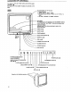
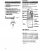
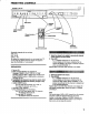
LOCATION OF CONTROLS For details on the use of each control, refer to the pages indicated in #. See page 10 for the location of jacks and controls on the back. mfi On screen display for the following: = Channel numbers / » “TAINT, “SAP or “BOTH” modes + The selected tout sources, “VIDEO “EXT-A" or “RGR" * The “AUX", “MUTING” or “SLEEP"” indicators. Hem display The cleansed item 10 be adjusted by the ADJUSTMENT buttons or the *RINGTONE” and “RESET” Indicators wail appear here.
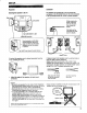
SET-UP Placement Attaching the speakers fo the TV Right speaker —W‘j \* / Left speaker Insiders \ Set BASS BOOST to ON SPEAKER terminals Turn the knobs on bath sides counterclockwise, adjust the finagle and then hurt the knobs clockwise 16 dock the speaker tn position. The “APP” bate! should be right side up.
Make s thé following are properly set, * ' Endorse “VIDEO EXT-A". or “RGB™* indicators and the' RGB or VIDEO lamp should be off. {Press VIDEO button ‘or RGB button as many rimes as necessary until: they. PO-out) + -AUTO STEREO elector should {depressed). Dependability oh the saccharine o be viewed, check the following. and change as.necessary. « CABLE ON/OFF button Forehand UHF changelings; set 1o OFF 0. For cable TV channels, Soreness “AUX"* indicator ..
Use of Forpdvataliswnlng headphones {optional) to the PHONES jack. The sound from the speakers-will be cut off automatically, PHONES (stereo tintypes) jack @ 1f the plug of your headphones Is a stereo phone-type plug, use the optional Sony PC-33 plug-adapter. Fox earphone can also be connected to listen to the monaural left channel) sound. {Hue: Color.
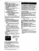
PRESETTING CHANNELS Controls on the TV. o0 7 ERASE button CABLE ONION button CHANNEL N scan buttons Remote Commander Receivable channels of your set are; VHF: 213 UHF: 14-69 1 Select the channel to be added by pressing the channel CATV: 1-128 number buttons and then ENTER. By adding and erasing channels, you can preset your TV 50 that only the desired channels appear in sequence when the CHANNEL are pressed. PREPARATION 1 Turn on TV, 2 Make sure the following are properly set.
APPLICATIONS WITH OTHER OPTIONAL EQUIPMENT This unit is equipped with various Input/output Jacks ang terminals for your desired equipment to disconnected. Forestalls on the various optional.
CONNECTIONS Externalizes AUDIO defector. if you have connected a VCR, video disc player, te, 1o the VIDEO 3 INPUT jacks, set to “VIDEO 3", 1f:you desire to mix the sound of the external audit source. disconnected. audio fracks with the picture of the TV program, set-to “EXT-AUDIO™: AUX {auxiliary} terminal TO CONVERTER terminal VILIFICATION antenna terminal See page 17.
‘Koo the VOR away from the TV, if the display or sound is affected. Connecting Coors that are capable of receiving TV Deadbolts VIDEO INPUT {mellow} 6 VIDEO 1 INPUT (VIDEO) @& {White} to VIDEO 1 INPUT AUDIO L Cm ion Television programs; films, vireo tapes and other materials may be copyrighted.
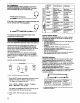
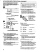
to RGB MULTI INPUT 34-pin plug Microcomputer * The connecting cable to be used depend upon the type of RGB output Jack of the computer. Tha cable should arrange the output signals of the computer 8o that they match the signal assignment of the RGB MULTI INPUT Microcomputer with video and audit outputs VMCE12MS Note 1 the display of the RGB signals are shifted off center to the right or left side of the screen adjust the H CENT control. 14 MKS-0001 {optional* RGE output connector of this unit (See page 19).
{f the “RGB” indicator misfit, press RGB button 10 turn it oft Press thg VIDEO button until the “VIDEO. 1, Dior 3% Indicator of the VIDEO input jacks trim which you desire the signals to core from “The VIDEO lamp. will light up. The picture of the selected VCR VIDEO lamp Every time you press the VIDEO button, the display will change as follows: VIDEO 1~ DIVED 2 — VIDEO 3* TV channel Adjust the volume with the VOLUME buttons. «Set VIDEO M EXT-AUDIC selector on the roar panel fo “VIDEO 8" It “EXT" appears.
ENJOYING FM SIMULCASTED PROGRAMMING Overthrow BN simulcasts Sometimes:a TV.station and'an FM radio station'will broadcast a program simultaneously so that viewers can enjoy TV programs In high-identity stereo. The video portion of ihe program is viewed rally by-selecting the comet channel and the adieu parson is heard In stereo by tuning to the correct FM station of the \tiers FM tuner.
ANTENNA/CABLE CONNECTION if you cannot obtain satisfactory reception with an indoor antenna, using an outdoor antenna may be necessary. Labile TV reception Is only possibility by connecting a cable supplied by your ioctl cable operator. Arapahos the antenna or cable end using the appropriate connector, and connect the antenna or cable to the antenna terminal of the TV.
HGB MULTI INPUT (pippin plug) g7y 5 V power supply Audio (7 Input ground Ground Remote control ground Composite video output groused ~| @ falsie Audio () input ground Ground 1 Ground 12%, 13+ Gourd 15 Ground Gourd Audio (R) input Mode select Com posits video output Audion} input Red Input Green input Blue input « Blanking Input * H, syn or composite sync 31 V.