
User Manual


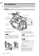
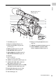


Table Of Contents
- Table of Contents
- Overview
- Preparations
- Recording
- Basic Operation Procedure
- Selecting the Video Format
- Switching the ND Filters
- Using the 5600K CC Filter
- Adjusting the White Balance
- Adjusting the Black Balance
- Displaying the Markers and Zebra Patterns
- Setting the Gain
- Setting the Electronic Shutter
- Adjusting the Iris
- Adjusting the Zoom
- Adjusting the Focus
- Reducing Flickers
- Setting the Time Data
- Recording Audio Signals
- Outputting the Color Bars and Reference Tone
- Recording Shot Marks
- Adding the OK Mark
- Rec Review
- Changing Functions of the Assignable Buttons
- Interval Recording
- Frame Recording
- Picture Cache Recording
- Slow & Quick Motion Recording
- Freeze Mix: Image Alignment
- Picture Profiles
- Deleting Clips
- Operating Planning Metadata
- Playback
- Thumbnail Screens
- Playing Back Clips
- Clip Operations
- Clip Operation Menus
- Basic Operations of the Clip Operation Menus
- Displaying the Detailed Information of a Clip
- Adding/Deleting the OK Mark to/from a Clip (HD Mode Only)
- Copying Clips
- Deleting Clips
- Displaying the EXPAND CLIP Screen
- Displaying the SHOT MARK Screen (HD Mode Only)
- Adding/Deleting Shot Marks (HD Mode Only)
- Changing the Index Frame (HD Mode Only)
- Dividing a Clip (HD Mode Only)
- Status Displays
- Menu Configuration and Detailed Settings
- Storing/Retrieving the Setting Data
- Connecting External Devices
- Appendixes

Parts Identifications
18
Overview
Connector block
1. HD SDI A/B (Dual-Link) connectors
(BNC type) (page 135)
2. DC IN (DC power input) connector
(page 23)
3. SDI OUT connector (BNC type) (page 134)
4. VIDEO OUT (analog video output)
connector (BNC type) (page 134)
5. TC IN (timecode input) connector (BNC
type) (page 141)
6. TC OUT (timecode output) connector
(BNC type) (page 142)
7. GENLOCK IN connector (BNC type)
(page 141)
8. HDMI OUT connector (page 134)
9. i.LINK (HDV/DV) connector (4-pin, S400
conforming to IEEE1394) (page 138)
10. USB connector (Mini B) (page 135)
11. Option connector (USB type A)
The optional CBK-WA01 Wi-Fi Adapter can
be connected.
For connection, refer to the Supplement in the
supplied CD-ROM labeled “Manuals for Solid-
State Memory Camcorder.”
For the mounting bracket for the Wi-Fi Adapter,
contact your Sony dealer or Sony service
representative.
12. REMOTE connector (8-pin)
An external remote control device, such as
the RM-B150/B750 Remote Control Unit,
can be connected.
For operation from the remote control device,
refer to the Supplement in the supplied CD-
ROM labeled “Manuals for Solid-State Memory
Camcorder.”
13. SPARE connector (10-pin)
It does not function at present.
Bottom
1. Tripod receptacles
Check that the size of the hole matches the
screw of the tripod. If they do not match, the
camcorder cannot be attached to the tripod
securely.
2. Backup battery holder (page 145)
3. Accessory mounting screw hole
Type of screw: 1/4-20UNC, length of
engagement: 10 mm (
13
/
32
inch) or less
Do not apply excessive force to the mounted
accessory. It may damage the screw thread.
MENU SEL/SET CANCEL
BATTERY
RELEASE
SDI OUT
VIDEO OUT
TC IN
TC OUT
GENLOCK IN
SLOT SELECT
ON OFF
PICTURE PROFILE
HD SDIAB
AB
DC IN
8
9
10
11
12
13
1
234567
Note
Note
123