4-740-705-11(1) Solid-State Memory Camcorder Operating Instructions Before operating the unit, please read this manual thoroughly and retain it for future reference.
Table of Contents Overview Location and Function of Parts ............................................... 7 Main unit ........................................................................ 7 Screen Display ......................................................................... 12 LCD/viewfinder screen ................................................ 12 Status screen ................................................................. 14 Preparation Power Supply ............................................
Shooting Basic Operation Procedure .................................................... 27 Shooting ....................................................................... 27 Adjusting the zoom ...................................................... 28 Adjusting the focus ...................................................... 29 Monitoring audio while shooting ................................. 30 Changing Basic Settings ......................................................... 30 Video format ...............
Connecting to Other Devices via LAN .................................. 54 Connecting using wireless LAN access point mode .... 54 Connecting using wireless LAN station mode ............. 55 Connecting to a device using a LAN cable .................. 57 Connecting to the Internet ..................................................... 59 Connecting using a modem .......................................... 59 Connecting using wireless LAN station mode (Wi-Fi station mode) ........................................
Filtering clips (frames) using the essence mark thumbnail screen (exFAT, UDF) ........................... 78 Changing the information displayed on the thumbnail screen ..................................................................... 78 Changing the index picture of a clip ............................ 78 External Device Connection Connecting External Monitors and Recording Devices ...... 79 External Synchronization .......................................................
Output Formats and Limitations ........................................ 132 Video formats and output signals ............................... 132 Network and video output combinations ................... 136 Limitations between recording functions ................... 136 Troubleshooting .................................................................... 137 Power supply .............................................................. 137 Recording/playback ....................................................
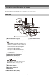
Overview Location and Function of Parts For details about the usage and function of each part, see the referenced page. Main unit 1. Hook for shoulder strap (10) 2. ASSIGN7/DIRECT MENU button (40) 3. (N mark) 11. Power zoom lever (28) 12. Wi-Fi antenna • Hold an NFC-compatible smartphone near this mark to establish a wireless connection between the camcorder and smartphone. For details, refer to the operating instructions of the smartphone.
1. Internal microphone (34) 2. Recording/tally lamp (front) (122) Flashes when the remaining capacity on the recording media or battery is low. 3. ASSIGN6 button 4. FULL AUTO button (27) 5. ND FILTER switch 6. ND FILTER mode switch 7. ASSIGN3/VIDEO SIGNAL MONITOR button 8. ASSIGN1/ZEBRA button 9. ASSIGN2/PEAKING button 10. INPUT1 switch (34) 11. CH1 (INT/EXT/MI SHOE) switch (34) 12. AUDIO LEVEL (CH1) dial (34) 13. AUDIO LEVEL (CH3) dial 14. AUDIO LEVEL (CH4) dial 15. AUDIO LEVEL (CH2) dial 16.
1. BATT RELEASE button (19) 2. Battery pack attachment (19) 3. Multi/Micro USB connector (81) 4. USB3.0 (HOST) connector (type A) 5. SDI OUT connector (79) 6. Diopter adjustment dial (22) 7. ON/STANDBY switch (20) 21. REMOTE connector The REMOTE connector is used for controlling start/stop of recording and other functions on the video device and peripherals connected to it. 22. Cable clamper Note • Do not use for any purpose other than securing cables. 23. GENLOCK IN/VIDEO OUT connector 24.
1. Zoom ring (29) 2. Focus ring (29) 3. Full MF switch (29) 20. MENU button (86) Button has a raised tactile bar for your convenience in locating the button. 21. WHT BAL switch (33) 22. GAIN switch (31) 23. ASSIGN10/IRIS PUSH AUTO button 24. ASSIGN9 button 25. FOCUS PUSH AUTO button (29) Switch manual focus mode on/off by moving the focus ring forward/back. 4. Lens cover lever (21) Opens/closes the lens cover. 5. MACRO switch (29) 6. FOCUS switch (29) 7. Hook for shoulder strap 8.
1. THUMBNAIL button (72) 2. STOP button (73) 3. STATUS CHECK button (14) 4. PREV button (73) 5. V/v/B/b/SET button (86) 6. MENU button (86) 7. F REV button (73) 8. PLAY/PAUSE button (73) 9. F FWD button (73) 10. NEXT button (73) 11. LCD BRIGHT button (22) 12. DISPLAY button (12) 13. LCD screen (22) 14. Viewfinder (22) 15. Large eyecup 16. Air inlet Bottom Side 1. Tripod screw holes (1/4 inch, 3/8 inch) Compatible with 1/4-20UNC screws and 3/816UNC screws.
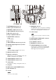
Screen Display LCD/viewfinder screen While recording, standing by to record, or during playback, the statuses and settings of the camcorder are superimposed on the LCD/viewfinder screen. You can show/hide the information using the DISPLAY button. You can also select to show/hide each item independently (page 105). Information displayed on the screen while shooting 1. Network status indicator (page 13) 9. Focus mode indicator (page 37) Displays the status of the network connection as an icon.
. SDI output/HDMI output Rec Control Information displayed on the playback screen The following information is superimposed on the playback picture. indicator Displayed when Display On/Off >SDI/HDMI Rec Control in the LCD/VF menu and SDI/ HDMI Rec Control >Setting in the Video menu are both set to On. 14. Digital extender indicator 15. Focus assist indicator 16. Media remaining capacity indicator 17.
Network mode Connection status Station mode Wi-Fi connected Modem Wi-Fi signal strength (4 levels) Wi-Fi disconnected (incl. during setup) Wi-Fi connection error 3G/4G signal strength (5 levels) 3 levels for modems without signal strength detection Camera Status screen Displays the picture quality, zoom settings, and status.
Headphone Out Headphone output type setting System Status screen Displays the video signal settings.
Media A remaining recording time Rec Button Settings Status screen Displays the setting status of the record button and handle record button. Displays an estimate of the remaining recording time of the recording media inserted in slot A in units of minutes under the current recording conditions.
Setting display Status display Description Station Mode Non Active Not operating in station mode. Displayed when Wi-Fi chip fails. Searching Disconnected NCM/Streaming Status screen Displays the connection status and streaming status in network client mode. Attempting to connect to the previously connected network (access point). Not connected to a network (access point). Also displayed when IP address was not assigned using DHCP. Connected to network (access point).
Status display Destination Directory Description Certificate has Expired The period of validity of the CCM certificate has expired. The network date and time settings may be incorrect. Root Certificate Error The root certificate is invalid. Note If this error message is displayed, contact your Sony service representative. Intermediate Cert. Error An intermediate certificate is invalid. Note If this error message is displayed, contact your Sony service representative.
Preparation Power Supply You can use a battery pack or AC power supply from an AC adapter. When an AC adapter is connected, the AC adapter has priority even when a battery pack is attached. For safety, use only the Sony battery packs and AC adaptors listed below. Checking the remaining capacity When recording or playback is in progress on the battery pack, an icon to show the current battery charge level and usage time remaining are displayed on the LCD/viewfinder screen (page 12).
Using AC power Turning the camcorder on/off Connecting the camcorder to a power outlet allows use without worrying about the need to recharge the battery pack. To turn the camcorder on, set the ON/STANDBY switch (page 9) to the ON position ([). To turn the camcorder off, set the ON/STANDBY switch to the STANDBY position (1). Notes • Even when the ON/STANDBY switch is set to the STANDBY position, the unit continues to draw standby electric power.
Setting the Clock Attaching Devices When you turn the camcorder on for the first time after purchasing or the backup battery has completely discharged, the initial setting display appears on the viewfinder screen and LCD screen. Set the date and time of the internal clock using this screen. Attaching the lens hood Time Zone The value shows the time difference from UTC (Coordinated Universal Time). Change the setting as required.
Diopter adjustment dial Move it until the picture becomes clear. Adjusting the Screens Adjusting the LCD screen Open the LCD screen 180 degrees (1), then rotate it to the best angle to record or play back (2). 1 Open 180 degrees 2 90 degrees (max.) Adjusting the brightness 2 180 degrees (max.) Adjust the brightness using VF Setting >Brightness (page 103) in the LCD/VF menu.
Note Using SxS Memory Cards • The memory card, memory card slot, and image data on the memory card may be damaged if the card is forced into the slot in the incorrect orientation. Removing an SxS memory card This camcorder records audio and video on SxS memory cards (sold separately) inserted in the card slots. 1 The EJECT button pops out. During recording, this will stop the recording. About SxS memory cards Supported memory cards 2 Use the following Sony SxS memory cards.
Using Format Media (page 110) in the Media menu, specify Media(A) (slot A) or Media(B) (slot B), then select Execute. When a confirmation message appears, select Execute again. Note • Up to approximately 600 clips can be recorded on one SxS memory card. If the number of recorded clips reaches the limit, an indication that the maximum number of clips has been reached is displayed. A message is displayed while formatting is in progress, and the access indicator is lit red.
Notes Using Other Media • For restoration of media recorded with this camcorder, be sure to use this camcorder. Media recorded with a device other than this camcorder or with another camcorder of different version (even of the same model) may not be restored using this camcorder. • Clips shorter than 2 seconds cannot be restored.
To execute formatting SDHC cards (FAT only) (Speed Class: Class 10) Using Format Media (page 110) in the Media menu, specify Media(A) (slot A) or Media(B) (slot B), then select Execute. Note • Not supported in exFAT and UDF modes. A message is displayed while formatting is in progress, and the access indicator is lit red. When formatting ends, a completion message appears. Formatting (initializing) SD cards must be formatted the first time they are used in the camcorder.
Shooting Basic Operation Procedure Continuous recording on the memory cards (Relay Rec) Shooting Basic shooting is conducted using the following procedure. 1 Attach the necessary devices, and check that power is being supplied. 2 Load the memory card(s). When memory cards are inserted in both slots A and B, recording automatically switches to the second memory card just before the remaining capacity on the first card is reduced to zero.
About clips Using the power zoom lever 1. Set the ZOOM switch D to SERVO. 2. Zoom by pressing the power zoom lever C. Clip (recording data) When you stop recording, video, audio, and subsidiary data from the start to end of the recording are recorded as a single clip on an SxS memory card. Lightly press the power zoom lever C for a slower zoom. Fully press it for a faster zoom.
Notes Using the zoom ring • Do not use excessive force at both ends of the travel when turning the focus ring. • While in Full MF mode, the auto focus and push auto focus functions do not work. • The macro is set to OFF regardless of the setting of the lens MACRO switch. 1. Set the ZOOM switch D to MANUAL. 2. Zoom by turning the zoom ring B. You can zoom at the desired speed by turning the zoom ring B. Fine adjustment is also possible.
magnifier screen appears showing the part of the image magnified. The magnification switches between 4× and 8× each time the button is pressed when the recording format is QFHD. You can move the magnified position using the V/v/B/b button. The center of the screen is magnified at a fixed 2× in recording formats other than QFHD. Press the button again to return to the normal screen. This function is useful for checking the focus.
Auto iris is active while the button is pressed. Release the button to return to manual iris mode. Note • You cannot change the format during recording or playback. Shooting with auto gain (AGC) Adjusting the brightness When Full Auto mode (page 27) is on AGC (Auto Gain Control) mode is forcibly enabled. When Full Auto mode is off Set Auto Exposure >AGC (page 92) in the Camera menu to On to activate AGC mode. You can also set AGC on/off in the direct menu (page 37). Shooting with fixed gain 1.
Setting in the Camera menu Select Shutter (page 92) in the Camera menu and set the shutter mode and speed. Setting auto exposure Auto exposure controls excessive brightness to an appropriate level using auto ND filter, iris, gain, and shutter functions. Set the control mode using Auto Exposure (page 92) >Mode in the Camera menu, and set the level using Level. You can also set the control mode and correction level in the direct menu (page 37).
Memory A mode, Memory B mode This mode adjusts the white balance to the setting saved in memory A or B, respectively. Press the WB SET button A to execute auto white balance adjustment and store the adjusted value in memory A or memory B. Using the direct menu Press the DISPLAY button (page 11) to display the selected mode and color temperature on the screen (page 12).
4 Audio source switches CH1 (INT/EXT/MI SHOE) switch D CH2 (INT/EXT/MI SHOE) switch I Press the WB SET button A. When you execute the adjustment in a memory mode, the adjusted value is stored in the memory (A or B) selected in step 1. If auto white balance is executed in ATW mode, the white balance adjustment returns to the ATW mode white balance when adjustment ends.
To record on CH3, CH4 1 Select INPUT1 using Audio Input (page 101) >CH3 Input Select and INPUT2 using CH4 Input Select in the Audio menu. 4 Attach a microphone, then close the microphone holder to secure the microphone. 5 Connect the microphone cable to the AUDIO INPUT1/AUDIO INPUT2 connectors (A/B). If INPUT1 is selected using CH4 Input Select, the sound from the AUDIO INPUT1 connector will be recorded on both CH3 and CH4.
Adjusting the audio recording level Time data Adjusting automatically (AGC) Setting the timecode Set the AUDIO LEVEL (CH1/CH2/CH3/ CH4) dials (E/H/F/G) to AUTO. Set the timecode to record using Timecode (page 107) in the TC/UB menu. You can set whether the levels on CH1 and CH2 are automatically adjusted separately (Mono) or together (Stereo) using Audio Input (page 101) >CH1&2 AGC Mode in the Audio menu.
2 Useful Functions Move the cursor to the desired item using the V/v/B/b button or SEL/SET dial, and press the SET button or SEL/ SET dial. Direct menu operation The direct menu for the selected item appears. You can check status and change settings for some items displayed directly on the LCD/ viewfinder screen. The Direct Menu function is used by assigning the function to an assignable button. The following items can be configured.
Notes Other faces (gray) • During push auto focus operation, Face Priority AF is activated even if Face Only AF is currently selected. • Face detection AF is not available in the following cases. In FULL MF mode When the FOCUS switch is set to MANUAL (excluding during push auto focus operation) When the recording format is DVCAM • If you turn the camcorder off while Face Only AF is selected, the mode automatically switches to Face Priority AF when the camcorder is next turned on.
Color bars/reference audio tone OK/NG/KEEP flags (exFAT, UDF) You can output color bars instead of the camera image by setting Color Bars (page 93) >Setting in the Camera menu to On. The image output is restored when set to Off. A 1 kHz reference audio tone can also be output with the color bars by setting Audio Input (page 101) >1kHz Tone on Color Bars in the Audio menu to On. The color-bar signal and reference-tone signal are output from the SDI OUT, HDMI OUT, and VIDEO OUT (color bars only) connectors.
• • • • • • • • • • • • • • • • • • • • • • • • • • • • • • Notes • Rec Review is not supported if the video format is changed after recording a clip. • The setup menus cannot be operated during Rec Review. • Rec Review is not available when the thumbnail screen displays the filtered clip thumbnail screen. Assignable buttons There are ten assignable buttons (page 7) on the camcorder to which you can assign functions. Changing functions Use Assignable Button (page 121) in the System menu.
Press the record button. Shooting interval (Interval Time) When you start recording, the “Int Stby” indication changes and alternates between “Int zRec” and “Int zStby.” Notes • While recording in Interval Rec mode, the Interval Time and Number of Frames settings cannot be changed. To change the settings, first stop recording. • After starting recording in Interval Rec mode, Rec Review operation is disabled, including during the interval time.
Notes Picture cache recording (Picture Cache Rec) • Clip Continuous Rec cannot be set to On at the same time as Interval Rec, Picture Cache Rec, S&Q Motion, 2-slot Simul Rec, or 4K & HD (Sub) Rec. When Clip Continuous Rec is set to On, these other recording modes are forcibly set to Off. • Clip Continuous Rec mode cannot be used while recording.
Notes Configuring before shooting • Changing the recording format clears the video in cache memory stored up to that point, and starts caching new video. Consequently, picture cache recording of pictures before changing format is not possible if you start recording immediately after changing format. • If Picture Cache Rec is started or stopped immediately after inserting an SxS memory card, cache data may not be recorded on the card.
• Rec Button: Button: Simultaneous recording in 2 slots (Simul Rec) Handle Rec To change the setting You can simultaneously record using both memory cards A and B. Select Simul Rec >Rec Button Set in the Recording menu. Configuring before shooting Rec Button Set Configure Simul Rec (page 108) in the Recording menu before shooting. Rec Button: Handle Rec Note Buttons and memory cards Starts/stops simultaneously recording to memory cards A and B using either button.
Gamma display assist function setting The LCD/viewfinder screen of the camcorder are not HDR compatible, and are not suitable for HDR display. Accordingly, the display can be made more visible for easier shooting using the gamma display assist function. You can change the setting of the gamma display assist function using Gamma Display Assist (page 105) in the LCD/VF menu.
5 If you press the CANCEL button during adjustment Automatic adjustment of the flange focal length is aborted and the condition before starting the adjustment is restored. Position the flange focal length adjustment chart or other high contrast object approximately 3 meters (10 ft) away from the camcorder, and arrange the lighting to obtain a satisfactory video output. If the flange focal length adjustment is not successful An error message appears.
SDHC memory cards* (Speed Class: 4 to 10, non-UHS / Capacity: 2 to 32 GB) SD memory cards* (Capacity: up to 2 GB) “Memory Stick PRO-HG Duo”** “Memory Stick PRO Duo”** Saving a user file / ALL file * Referred to as “SD card” in this document. ** Referred to as “Memory Stick” media in this document. 1 Insert the SD card or “Memory Stick” media into the UTILITY SD/MS slot (page 9) with the label facing right. 2 For a user file, select User File (page 112) >Save Utility SD/MS >Execute in the File menu.
4 4 Select Execute using the V/v/B/b button or SEL/SET dial, and press the SET button or SEL/SET dial. Notes • The camcorder will reboot automatically after loading configuration data. • When All File >Load Network Data in the File menu is set to Off, all settings in the ALL file are loaded except the Network menu settings.
To change the File ID Loading a planning metadata file 1 To record planning metadata together with clips, it is necessary to load a planning metadata file into the camcorders memory beforehand. For a user file, select User File >File ID in the File menu (page 112). For an ALL file, select All File >File ID in the File menu (page 112). For a scene file, select Scene File >File ID in the File menu (page 112). Note • Data cannot be loaded from an SDXC/SDHC card.
The shaded fields in the example are clip name strings. “Typhoon” is described in ASCII format (up to 44 characters). “Typhoon_Strikes” is described in UTF-8 format (up to 44 bytes). “sp” indicates a space and 3 indicates a carriage return. Notes • If the serial number reaches 99999, it returns to 00001 upon the next recording. • When you load another planning metadata file, the 5digit serial number returns to 00001. Defining shot mark names in planning metadata
Note • When you create a file, enter each statement as a single line by breaking a line with a carriage return only after the last character of the line, and do not enter spaces except where specified with “sp” outside the shot mark name strings. • • Acquiring location information (GPS) Location and time information of video shot when positioning is enabled is recorded onto media loaded in the card slot of the camcorder, and can be output as SDI. • • 1. Press the MENU button during standby. 2.
Checking the remaining capacity Proxy Recording You can check the remaining capacity on an SD card on the Media Status screen (page 15). You can record proxy data on an SD card simultaneously while recording on an SxS memory card. Note • A Supported SD cards First, make a backup of the card, then reformat the card in the device to be used.
Changing proxy recording settings Setting the picture size Select Proxy Rec >Proxy Format in the Recording menu, and set the picture size. Set Proxy Rec >Setting in the Recording menu to On. 3 Insert the SD card media into the UTILITY SD/MS slot (page 9) with the label facing right. Recording Setting the audio channel Start the recording after completing the required setting. Select Proxy Rec >Audio Channel in the Recording menu, and set the audio channel for proxy recording.
* XDCAM air is a cloud service that is provided by Sony. To use this service, registration is required. XDCAM air is not provided in some regions. For details on areas where the service is provided, refer to the following site. https://www.xdcam-air.com For more details, contact a Sony professional sales representative. Connecting to Other Devices via LAN The camcorder can connect to smartphones, tablets, and other devices using via LAN connection.
3 • For the SSID and password of the camcorder, check AP Mode Settings (page 114) >Camera SSID & Password in the Network menu. Activate the NFC function. Press and hold (for 3 seconds) an assignable button assigned with NFC or select Wireless LAN >Wi-Fi >NFC in the Network menu to activate NFC connection mode. The NFC function is available only while appears on the screen. 4 5 Display the web remote control (page 68). Or connect using the Content Browser Mobile application.
6 Smartphone/ tablet Computer Connect the device to the access point. For details about connecting, refer to the operating instructions of the device. 7 Display the web remote control (page 68). Or connect using the Content Browser Mobile application. Connecting to an access point using auto network detection or manually Access point You can configure connection to a desired access point from the setup menu.
• IP Address Input the IP address of the camcorder. This setting is available only when DHCP is set to Off. • Subnet Mask Input the subnet mask of the camcorder. This setting is available only when DHCP is set to Off. • Gateway Input the default gateway for the access point. This setting is available only when DHCP is set to Off. • DNS Auto Set to acquire DNS automatically. When set to On, the DNS server address is automatically acquired. This setting is available only when DHCP is set to On.
3 Set Wired LAN (page 115) >Setting in the Network menu to On. 4 Configure connection settings using Detail Settings in the menu. Computer • DHCP Set the DHCP setting. When you set to On, the IP address is assigned to the camcorder automatically. To assign the IP address to the camcorder manually, set to Off. • IP Address Input the IP address of the camcorder. This setting is available only when DHCP is set to Off. • Subnet Mask Input the subnet mask of the camcorder.
Note Connecting to the Internet • It may take some time (about 1 minute) to connect to a 3G/4G network. Wait until the network status indicator (page 12) “3G/4G” icon shows a strength of 1 or higher on the LCD/viewfinder screen. You can connect the camcorder to the Internet using a modem, wired LAN, or wireless LAN.
Connecting using a LAN cable You can connect with a device by connecting the wired LAN connector of the camcorder to an Internet router using a LAN cable. Computer Router Internet Connect to the Internet router as described in “Connecting to a device using a LAN cable” (page 57).
List of functions for network connections The following table shows the availability of network functions in each network connection mode.
Note Uploading a File • When editing, “s” indicates characters that cannot be changed. Correct operation is not guaranteed when editing a directory name that contains these characters. If you need to edit, delete all the characters and re-enter a value. You can upload a proxy file or original file that is recorded on the camcorder to a server on the Internet or a server on a local network via a 3G/ 4G network or access point. Using Secure Protocol Set whether to perform secure FTP uploading.
6 Uploading a proxy file on an SD card 1 Connect the camcorder and device using a LAN connection (page 54). 2 Launch a browser on the device and display the web remote control (page 68). 3 Display the file list screen to select a file. Tap Transfer. The camcorder starts uploading the selected file. To cancel uploading, tap Cancel. Uploading an original file on an SxS memory card Tap >File Transfer >Slot SD/MS. A file list screen for the media inserted in the UTILITY SD slot appears.
Checking the file transfer Transmitting Streaming Video and Audio You can check the upload status on the Job List screen that is displayed by tapping Job List on the SD Card, Slot A, or Slot B screen (page 71). Notes You can transmit the video and audio recorded/ played back with the camcorder via the Internet or local network. • Up to 200 transfer jobs can be registered.
• • • • • • CH1/CH2 CH3/CH4 CH1 CH2 CH3 CH4 Notes • Streaming cannot be started under the following menu settings.
Notes Network client mode • Set the clock of the camcorder to the correct time before loading CCM and XDCAM air connection certificates. • When recording in XAVC-I 3840×2160P 59.94/ 50P, Load cannot be selected. • In low voltage state, CCM and XDCAM air connection certificates cannot be loaded or cleared. High-quality streaming is supported by enabling network client mode and connecting a Sony Network RX Station (option) as a Connection Control Manager (CCM) or connecting via XDCAM air.
• • • • • • • • • • • • 3 When S&Q Motion >Setting in the Recording menu is set to On When Interval Rec >Setting in the Recording menu is set to On When Simul Rec >Setting in the Recording menu is set to On Changing to network client mode during normal streaming (page 64) is not possible. After changing to network client mode, normal streaming and monitoring (page 69) are not available. Changing to network client mode while monitoring will stop the monitoring.
Playback screen Using Web Remote Control You can access the web remote control built into the camcorder from a tablet or computer over a network connection. Using the web remote control allows you to operate the camcorder remotely. You can start/ stop recording and adjust the recording settings with a connected device. This function is useful for setting the camcorder in a remote place, such as the top of a crane, etc.
2 Launch a browser on the device, then access “http://IP address of camcorder/ rm.html.” Web Remote Control Menu Example: When the IP address is 192.198.122.1, input http://192.168.1.1/ rm.html in the address bar. You can check the IP address of the camcorder on the Network Status screen (page 16). 3 Tapping in the top left of the Camera Control screen will display the screen selection menu. Select Monitoring Settings to display the Monitoring Settings screen.
Password File transfer settings (Upload Settings) Enter the password. Passive Mode Turn passive mode on/off. You can change the server settings for uploading a proxy file or an original file that is recorded on the camcorder. Destination Directory Enter the directory on the destination server. Using Secure Protocol Set whether to perform secure FTP uploading. Setting to ON displays the certificate status. To import or clear a certificate, tap Select Function and select a task in the displayed menu.
• Start selected: Start uploading the selected file. • Select All: Select all files in the list. • Clear completed: Delete the list of uploaded files. Transferring files (Slot A, Slot B, Slot SD/ MS) Displays a list of clips recorded on media inserted in slot A/slot B or a list of proxy files recorded on media inserted in the UTILITY SD/MS slot. You can select a displayed file to upload the file to a server on the Internet. For details about uploading files, see “Uploading a File” (page 62).
Thumbnail Screen Configuration of the Thumbnail Screen When you press the THUMBNAIL button (page 11), clips recorded on the SxS memory card are displayed as thumbnails on the screen. You can select a clip on the thumbnail screen and start playback of that clip. The playback picture can be seen on the LCD/viewfinder screen and external monitors. Pressing the THUMBNAIL button again closes the thumbnail screen and returns to the camera image.
Notes Playing Clips • There may be momentary picture breakup or still image display at the boundary between clips. You cannot operate the camcorder during this period. • When you select a clip in the thumbnail screen and begin playback, there may be momentary picture breakup at the start of the clip. To start playback without distortion, pause playback once after starting it, press the PREV button of the playback control buttons to return to the top of the clip, then restart playback.
Clip Operations The Thumbnail menu is used to protect/delete clips, check properties, add/delete clip flags in a clip, and other tasks. Thumbnail menu operations The Thumbnail menu can be used only when a thumbnail screen is displayed. 1 Press the THUMBNAIL button. The thumbnail screen appears. 2 Press the MENU button. The menu screen appears. 3 Select Thumbnail using the V/v/B/b button or SEL/SET dial, and press the SET button or SEL/SET dial.
Displaying clip properties Select Display Clip Properties in the Thumbnail menu. 1. Image of the current clip 2. Timecode indicator TC Index: Timecode of the displayed frame Start: Timecode at the recording start point End: Timecode at the recording end point Duration: Duration of the clip 3. Creation date and modified date 4. Currently selected memory card 5. Media protect icon 6. Clip number/Total number of clips 7. Battery icon 8.
3 Protecting clips (exFAT, UDF) You can protect a specified clip or all clips to protect the clips from being deleted. is added to the thumbnails of protected clips. Clips can be protected on the thumbnail screen or the filtered clip thumbnail screen (page 77). Copying clips You can copy clips to another SxS memory card. Clips are copied to destination SxS memory cards using the same names as the original clips.
2 Copying all clips All clips are deleted, and a completion message appears. You can copy all clips stored on the same SxS memory card at the same time to another SxS memory card. 1 3 Select Copy Clip > All Clips >Execute in the Thumbnail menu. Select Execute. All clips are copied, and a completion message appears. 3 Press the SET button or SEL/SET dial to dismiss the message. Adding/deleting clip flags (exFAT, UDF) A confirmation screen appears. 2 Select Execute.
Selecting Filter Clips >All on the Thumbnail screen cancels the filtering, and returns to the clip thumbnail screen. You can also switch using the DISPLAY button. If a clip is recorded using planning metadata that defines names for shot mark 0 to shot mark 9, the selection options in the list are displayed by the defined names. Deleting shot marks (exFAT, UDF) Changing the information displayed on the thumbnail screen You can delete shot marks added to a clip.
External Device Connection Connecting External Monitors and Recording Devices To display recorded/playback pictures on an external monitor, select the camcorder output signal and use an appropriate cable for the monitor to be connected. You can also connect recording devices, such as a VTR, and record the output signal from the camcorder. You can display the same information that is visible in the viewfinder, such as status information and menus, on an external monitor.
1 External Synchronization Mode: Preset Run: Free Run When multiple units of the camcorder are used in the same shooting location, recording can be synchronized with a specific reference signal, and the timecode can be matched among all the units. Synchronizing the phase of the video signals (genlock) Genlock operation is enabled by supplying a reference signal to the GENLOCK IN/VIDEO OUT connector (page 9) of the camcorder.
To release external lock Change the Timecode setting in the TC/UB menu or set the camcorder to STANDBY. External synchronization is also released if the system frequency is changed and when you start recording in a special recording mode (Slow & Quick Motion or Interval Rec). Managing/Editing Clips on a Computer Connecting using a USB cable Synchronizing the timecode of another unit to the timecode of your camcorder 1 Set the timecode of the camcorder using Timecode (page 36) in the TC/UB menu.
called “NO NAME” or “Untitled” (editable) is created on the Desktop. Copying clips to USB media Notes • Do not perform the following operations if the access lamp is lit red. Turning the power off or disconnecting the power cord Removing the SxS memory card Disconnecting the USB cable • When removing an SxS memory card from a Macintosh, do not select “Card Power Off” from the SxS memory card icon displayed on the menu bar. • Operation is not guaranteed with all computers.
menu. To start the supply of power, perform the solution shown in the table. Renaming a folder on an external HDD/ USB media 1 Select USB >Rename Folder (page 110) in the Media menu. 2 Select the folder to rename from the folder list, and press the SET button or SEL/SET dial. State A file name input screen appears. 3 Solution Terminate the previous During clip recording, playback, thumbnail display, operation.
Menu Display and Settings Setup Menu Configuration and Hierarchy Press the MENU button to display the setup menu on the LCD screen/viewfinder to specify various items for shooting, recording, and playback (menu can also be displayed on an external monitor). The setup menu comprises the following menus. User Menu: Menu with items configured by the user (edit using Edit User Menu). Edit User Menu menu: Menu for editing User menu items. Camera menu: Contains settings related to shooting.
Video Output On/Off Output Format Output Display SDI/HDMI Rec Control Down Converter LCD/VF LCD Setting VF Setting Peaking Marker Zebra Gamma Display Assist Display On/Off TC/UB Timecode Users Bit HDMI TC Out Recording S&Q Motion Interval Rec Picture Cache Rec Clip Continuous Rec Simul Rec 4K & HD (Sub) Rec Proxy Rec Rec Review Thumbnail Display Clip Properties Set Shot Mark Set Clip Flag Lock/Unlock Clip Delete Clip Copy Clip Copy Sub Clip Set Index Picture Thumbnail View Filter Clips Customize Vi
Entering a character string Setup Menu Operations When you select an item, such as a file name, which requires character entry, the character entry screen appears. Press the MENU button to display the setup menu on the LCD screen/viewfinder to specify various items for shooting, recording, and playback (menu can also be displayed on an external monitor). 1 Menu controls MENU button (page 10) Turn menu mode on/off for setup menu operation.
Note • When only the MENU button is pressed to display the normal setup menu, User Menu Only is displayed under Menu Settings in the System menu. Press and hold the SEL/SET dial and press the MENU button to display User Menu with Lock. 3 Set to On, and press the SET button or SEL/SET dial. The LCD/viewfinder screen display switches to the passcode number input screen. 4 Enter an arbitrary number. Enter a 4-digit number in the range 0000 to 9999. The default value is 0000.
3 Note Place a check mark in the All checkbox to add all sub-items. Place a check mark in the individual checkboxes to specify which sub-items to add. • When only the MENU button is pressed to display the normal setup menu, User Menu Only is displayed under Menu Settings in the System menu. Press and hold the SEL/SET dial and press the MENU button to display User Menu with Lock. 3 4 Set to Off, and press the SET button or SEL/SET dial. Note • The same item or sub-item cannot be registered twice.
2 Select Move. The item to move is highlighted, and a triangle mark and line indicate the destination position. 3 Move the triangle mark and line to the destination of the item, and press the SET button or SEL/SET dial. The item is moved. Restoring the User menu to factory default state 1 Select Edit User Menu >Customize Reset in the User menu. The Customize Reset screen appears. 2 Select Reset, and press the SET button or SEL/SET dial. A confirmation screen appears.
Setup Menu List This section describes the function and settings of the items in each menu. Factory default settings are shown in bold (for example, 18dB).
Camera menu Camera Item Sub-items and Settings Focus Description Face Detection AF Face Only AF / Face detection AF Face Priority AF / Off settings Enables/disables face detection AF. ND Filter Preset1 1/128 / 1/64 / 1/32 / 1/16 / 1/8 / 1/4 Sets the preset 1 value of the ND filter. Preset2 1/128 / 1/64 / 1/32 / 1/16 / 1/8 / 1/4 Sets the preset 2 value of the ND filter. Preset3 1/128 / 1/64 / 1/32 / 1/16 / 1/8 / 1/4 Sets the preset 3 value of the ND filter.
Camera Item Sub-items and Settings Description Shutter Mode Speed / Angle Selects the operating mode of the electronic shutter. Used for shooting fast-moving subjects clearly. Selects the mode for setting the shutter speed in seconds (Speed) or as a shutter angle (Angle). Electronic shutter operating condition settings Sets the shutter speed when Speed mode is selected.
Camera Item Sub-items and Settings Auto Exposure Auto Shutter Brightness automatic exposure settings Color Bars Color bar settings Description Turns the auto shutter control function on/off. On / Off A.SHT Limit 1/100 / 1/150 / 1/200 / 1/250 / 1/2000 Sets the fastest shutter speed of the auto shutter function. A.SHT Point F5.6 / F8 / F11 / F16 Sets the F-stop value of the iris where auto shutter operation starts.
Camera Item Sub-items and Settings Description Auto FB Adjust Auto FB Adjust Execute / Cancel Executes automatic focal length (flangeback) adjustment. The camcorder automatically adjusts the focal length to ensure subjects are maintained in focus from wide angle to telephoto ends of the lens zoom. Video Light Set Power Link / Rec Link / Rec Link + Stby Sets the lighting control method for the video light attached to the Multi Interface Shoe.
Paint Item Sub-items and Settings Description White Preset White 10000K to 2100K (3200K) Adjusts the preset color temperature when a preset is selected in white balance mode. White balance settings Note • You cannot check the change on the screen even if the Preset White setting is changed when a preset is not selected in white balance mode. White Setting White balance adjustment settings Color Temp 50000K to 1500K (3200K) Displays the white balance color temperature saved in memory A.
Paint Item Sub-items and Settings Description Offset White Offset White On / Off Selects whether to add (On) or not to add (Off) an offset value to the white balance in memory A. Warm Cool –99 to +99 (±0) When Offset White is set to On, this specifies the offset (as a color temperature) to add to the white balance in memory A. (Note that the error increases for higher offset color temperatures. Adjust while viewing the actual image.
Paint Item Sub-items and Settings Black Gamma Setting Black gamma level adjustment settings On / Off Description Turns the black gamma correction function on/off. Note • The Black Gamma and Knee >Knee Saturation functions cannot be used at the same time. Low Key Saturation Range Low / L.Mid / H.Mid Selects the effective range of the black gamma correction. Master Black Gamma –99 to +99 (±0) Sets the master black gamma level.
Paint Item Sub-items and Settings Description White Clip Setting On / Off Turns white clipping adjustment function on/off. White clip adjustment settings Level 90.0% to 109.0% Sets the white clip level. Detail(QFHD) Manual Setting On / Off Turns the detail adjustment function on/off. Level –99 to +99 (±0) Sets the detail level. H/V Ratio –99 to +99 (±0) Sets the mix ratio between the H detail level and the V detail level. Crispening –99 to +99 (±0) Sets the crispening level.
Paint Item Sub-items and Settings Description Detail(SD) Manual Setting On / Off Turns the detail adjustment function on/off. Level –99 to +99 (±0) Sets the detail level. H/V Ratio –99 to +99 (±0) Sets the mix ratio between the H detail level and the V detail level. Crispening –99 to +99 (±0) Sets the crispening level. Frequency –99 to +99 (±0) Sets the center frequency of the detail (detail thickness).
Paint Item Sub-items and Settings Description Matrix Setting On / Off Turns the matrix correction function on/off. Adaptive Matrix On / Off Turns the adaptive matrix function on/off. Preset Matrix On / Off Turns the preset matrix function on/off. Matrix correction settings Selects a preset matrix. Preset Select 1:SMPTE 240M / 2:ITU-709 / 3:SMPTE Wide / 4:NTSC / 5:EBU / 6:PAL User Matrix On / Off Turns the user matrix correction function on/off.
Audio menu Audio Item Sub-items and Settings Description Audio Input CH2 EXT Input Select INPUT1 / INPUT2 Selects the input for recording on channel 2. Enabled only when the EXT audio source is selected. Audio input settings CH3 Input Select Selects the input for recording on channel 3. Off / INPUT1 / Internal MIC / Shoe CH1 CH4 Input Select Off / INPUT1 / INPUT2 / Internal MIC / Shoe CH2 Selects the input for recording on channel 4.
Audio Item Sub-items and Settings Audio Output Monitor CH Selects the audio channel output to the headphone jack and CH1/CH2 / CH3/CH4 / MIX built-in speaker. ALL / CH1/ CH2 / CH3 / CH4 Audio output settings Description Headphone Out Mono / Stereo Sets the headphones output to monaural (Mono) or stereo (Stereo). Alarm Level 0 to 7 (4) Sets the alarm volume. HDMI Output CH CH1/CH2 / CH3/CH4 Selects the combination of audio channels on the HDMI output.
LCD/VF menu LCD/VF Item Sub-items and Settings Description LCD Setting Brightness –99 to +99 (±0) Adjusts the brightness of the LCD screen. Brightness –99 to +99 (±0) Adjusts the brightness of the viewfinder image. Color Mode Color / B&W Selects the display mode of the viewfinder in E-E/recording mode. Setting On / Off Turns the peaking function on/off. Type Normal / Color Selects the peaking type.
LCD/VF Item Sub-items and Settings Description Marker Setting On / Off Turns the display of all markers on/off. Marker display settings Color Selects the marker display color. White / Yellow / Cyan / Green / Magenta / Red / Blue Center Marker 1 / 2 / 3 / 4 / Off Turns the center marker on/off. Safety Zone On / Off Turns the safety zone marker on/off. Safety Area 80% / 90% / 92.5% / 95% Selects the size of the safety zone marker (as a percentage of total screen size).
LCD/VF Item Sub-items and Settings Description Zebra Setting On / Off Turns the zebra function on/off. Zebra Select 1 / 2 / Both Selects the zebra pattern type (Zebra1, Zebra2, Both). Zebra1 Level 0% to 107% (70%) Sets the Zebra1 display level. Zebra1 Aperture Level 1% to 20% (10%) Sets the Zebra1 aperture level. Zebra2 Level 0% to 109% (100%) Sets the Zebra2 display level.
LCD/VF Item Sub-items and Settings Description SteadyShot On / Off Gamma On / Off SDI/HDMI Rec Control On / Off Gamma Display Assist On / Off Proxy Status On / Off Focus Assist Indicator On / Off Focus Assist Area On / Off Media Status On / Off Video Signal Monitor Off / Waveform / Vector / Histogram Clip Name On / Off White Balance On / Off Scene File On / Off Auto Exposure Mode On / Off Auto Exposure Level On / Off Timecode On / Off ND Filter On / Off Iris On / Off Gain On / Off Shutter On / Off Audio
TC/UB menu TC/UB Item Sub-items and Settings Timecode Mode Preset / Regen / Clock Timecode settings Users Bit User bits settings HDMI TC Out Description Sets the timecode running mode. Preset: Starts the timecode from the specified value. Regen (regeneration): Starts the timecode by continuing the timecode of the previous clip. Clock: Uses the internal clock as the timecode. Run Rec Run / Free Run Rec Run: Runs only when recording. Free Run: Always running, regardless of camcorder operation.
Recording Item Sub-items and Settings Description Interval Rec Setting On / Off Interval recording mode settings Interval Time Turns interval recording mode on/off. Selects the interval between recordings in Interval Rec mode 1sec / 2sec / 3sec / 4sec / 5sec / (when Interval Rec is set to On).
Recording Item Sub-items and Settings Description Proxy Rec Setting On / Off Turns proxy recording mode on/off. Proxy Format 1920×1080(9Mbps) / 1280×720(9Mbps) / 1280×720(6Mbps) / 640×360(3Mbps) / 480×270(1Mbps) / 480×270(0.5Mbps) Sets the picture size for the proxy file. When set to 1920×1080(9Mbps) and the system frequency is 23.98, recording uses progressive scan. For system frequencies other than 23.98, recording uses interlaced scan.
Thumbnail Item Sub-items and Settings Description Thumbnail View Displays thumbnails of frames with essence marks. Essence Mark Thumbnail All / Rec Start / Shot Mark1 / Shot Mark2 / Shot Mark3 / Shot Thumbnail screen Mark4 / Shot Mark5 / Shot display settings Mark6 / Shot Mark7 / Shot Mark8 / Shot Mark9 / Shot Mark0 Clip Thumbnail Displays thumbnails of recorded clips. Filter Clips OK Displays only clips that have an OK flag.
Media Item Sub-items and Settings Clip Naming Auto Naming Title / Plan Settings relating to clip naming and deletion Title Prefix nnn_ (nnn is the last 3 digits of the serial number) (Max. 7-digit display) Description Selects the clip naming format. Title: Sets naming specified by Title Prefix. Plan: Uses a name specified in planning metadata, if available. If no name is specified in planning metadata, the name specified by Title Prefix is used.
Media Item Sub-items and Settings Planning Metadata Load Media(A) or Settings relating to Load Media(B) Execute / Cancel planning metadata operations Description Loads planning metadata from the SxS memory card in slot A or B. Select Execute to display the list of the planning metadata files stored on the SxS memory card in slot A or B. Select a file using Load and then select Execute to load the file. Notes • The file list displays up to 64 files.
File Item Sub-items and Settings Description All File Load Utility SD/MS Execute / Cancel Loads an ALL file. Execute: Execute function. Save Utility SD/MS Execute / Cancel Saves an ALL file. Execute: Execute function. ALL file settings Scene File Scene file settings File ID Assigns a name to the file. Load Network Data On / Off Sets whether to load Network menu settings information when Load Utility SD/MS is executed.
Network Item Sub-items and Settings Description AP Mode Settings Channel Sets the wireless LAN channel. Auto(5GHz) / Auto / CH1 / Auto(5GHz) is available on the PXW-Z280V only. CH2 / CH3 / CH4 / CH5 / CH6 Access point mode / CH7 / CH8 / CH9 / CH10 / connection settings CH11 ST Mode Settings Camera SSID & Password Displays the SSID and password of the camcorder. Regenerate Password Execute / Cancel Creates a new password. Execute: Execute function.
Network Item Sub-items and Settings Description Wired LAN Setting On / Off Turns the wired LAN function on/off. Wired LAN connection settings Camera Remote Control Enable / Disable Detail Settings Modem settings Configures properties of the wired LAN connection. DHCP On / Off Turns DHCP on/off. IP Address Enter the IP address of the camcorder when DHCP is set to Off. Subnet Mask Enter the subnet mask of the camcorder when DHCP is set to Off.
Network Item Sub-items and Settings Description File Transfer Auto Upload (Proxy) On / Off Turns proxy file auto transfer on/off. Auto Upload Server Selects the auto upload server for proxy files. Displays the display name configured in Server Settings(NCM) and Server Settings1 to Server Settings3. Clear Completed Jobs Execute / Cancel Clears completed transfer jobs from the list. Execute: Execute function. Clear All Jobs Execute / Cancel Clears all transfer jobs from the list.
Network Item Sub-items and Settings Description Streaming Setting On / Off Starts (On) or stops (Off) streaming. Destination Select Selects preset settings (Destination Settings1/Destination Settings2/Destination Settings3) comprising streaming destination settings configured beforehand. Destination Settings1 Display Name Enter the display name shown in the streaming destination setup menu. Streaming Type Displays the streaming method of the streaming destination (display only).
System menu System Item Sub-items and Settings Description Base Setting Shooting Mode SDR / HDR Selects the dynamic range mode. Rec/Out HDR(HLG) / HDR(S-Log3) Selects recording in HDR mode and the gamma curve of the output signal. Frequency 59.94 / 50 / 29.97 / 25 / 23.98 (NTSC Area: 59.94, PAL Area: 50) Selects the system frequency. File System exFAT / UDF / FAT Selects the file system. Codec XAVC-I / XAVC-L / MPEG HD 422 / MPEG HD 420 / DVCAM(MXF) Sets the recording/playback mode.
System Item Sub-items and Settings 50 29.97 25 23.
System Item Sub-items and Settings Description UDF MPEG HD422 1920×1080i 50 1280×720P 50 MPEG HD420 1920×1080i HQ 1440×1080i HQ 1280×720P HQ 59.94 50 29.97 25 23.
System Item Assignable Button Sub-items and Settings <1> to <10> Push AF/Push MF / Face Detection AF / ND Filter Assignable button Position / Auto ND Filter / Push function Auto ND / Push Auto Iris / assignment Turbo Gain / AGC / Shutter / settings Auto Exposure Level / Spotlight / Backlight / Flash Band Reduce / Digital Extender ×2 / Handle Zoom / Color Bars / Preset White Select / ATW / ATW Hold / Marker / Zebra / Peaking / Video Signal Monitor / Focus Magnifier / Lens Info / LCD/VF Adjust / VF Mode / G
System Item Sub-items and Settings Description Rec Review: Starts recording review. Last Clip Delete: Executes the last clip delete (retake) function. Thumbnail: Turns the thumbnail screen display on/off. Shot Mark1: Adds shot mark1 to the currently recording or playing clip. Shot Mark2: Adds shot mark2 to the currently recording or playing clip. Clip Flag OK: Adds/deletes an OK flag to/from the currently recording or playing clip.
System Item Sub-items and Settings Description DC Voltage Alarm DC Low Voltage1 11.2V to 14.0V (11.3V) Sets the voltage to display a DC IN low input voltage alarm (0.1V increments). DC IN input lowvoltage alarm settings DC Low Voltage2 11.0V to 14.0V Sets the voltage to display a DC IN input undervoltage alarm (0.1V increments). Menu Settings Direct Menu with Menu settings On / Off Sets whether to start direct menu operation by pressing the SET button.
Appendix Important Notes on Operation About the battery pack Using your camcorder abroad To charge the battery pack • Be sure to charge the battery pack before you start using your camcorder. Power supply You can use your camcorder in any country/ region using the BC-U1A (supplied) or optional BC-U2A charger within the AC 100 V to 240 V, 50 Hz/60 Hz range.
About charging the battery pack • Use the Charger (supplied) to charge the designated batteries only. If you charge other types of batteries, those batteries may leak, heat up, burst, or give an electric shock, resulting in burns or injury. • Remove the charged battery from the Charger. • The charge lamp of the supplied Charger flashes in 2 patterns as follows: Fast-flashing...Turns on and off rapidly at about 0.15-second intervals. Slow-flashing...Turns on and off alternately for about 1.
wash off any liquid that may have contacted your skin. if any liquid gets in your eyes, wash with plenty of water and consult a doctor. To clean the LCD screen The surface of the LCD screen is coated. If you scratch the surface, the coating may be come off. Mind the following points when cleaning and handling it. • If hand grease or hand cream remains on the screen, the coating comes off more easily. Wipe it early. • The coating may be scratched if you wipe the screen with a tissue, etc.
connected or the battery pack attached. Use your camcorder after charging the pre-installed rechargeable battery. However, even if the pre-installed rechargeable battery is not charged, the camcorder operation will not be affected as long as you are not recording the date. These colors are not recorded onto the memory cards. About consumable parts • The fan and battery are consumable parts that will need periodic replacement.
24 or more GPS satellites. A GPS receiver receives radio signals from the satellites, and calculates the current location of the receiver based on the orbital information (almanac data) and travel time of the signals, etc. Determining a location is called “triangulating.” A GPS receiver can determine the location’s latitude and longitude by receiving signals from 3 or more satellites. Notes on Internet security • Use the camcorder behind a firewall that is designed with safety.
current location when the camcorder receives radio signals from 3 or more GPS satellites. The triangulating error allowed by the GPS satellites is about 10 m (33 feet). Depending on the environment of the location, the triangulating error can be greater. In this case, your actual location may not match the location on the map based on the GPS information. Meanwhile, the GPS satellites are controlled by the United States Department of Defense, and the degree of accuracy may be changed intentionally.
Video Formats About recording media Recording media and compatible formats x Normal recording XAVC-I XAVC-L MPEG HD422 MPEG HD420 DVCAM File system SxS Pro+ SxS Pro SxS-1 XQD SDXC SDHC exFAT 3840×2160 a – – – – 1920×1080 a a – – – – 1280×720 a – – – – – 3840×2160 a a a a – – 1920×1080 a a a a a – 1280×720 a a a a a – exFAT a a a a a – UDF a a a a – – exFAT a a a a a – UDF a a a a – – FAT – – – – – a exFAT a a a a a
Special recording modes and compatible formats XAVC-I XAVC-L MPEG HD422 MPEG HD420 exFAT exFAT exFAT UDF exFAT UDF FAT Interval Rec a a a – a – – – Clip Continuous Rec a a a a a a – – Picture Cache Rec a a a a a a a – Slow & Quick Motion a a a – a – – – 2-slot Simul Rec a a a a a a – – 4K & HD (Sub) Rec a a – – – – – – a: Compatible –: Incompatible Maximum recording time for a clip Recording format Continuous recording Relay Rec maximum time (per
Output Formats and Limitations Video formats and output signals SDI OUT connector output formats Recording format setting SDI output setting Output signal/Conversion method Rec Format >Frequency in the System menu Rec Format >Video Output Format >SDI in Output signal Format in the System the Video menu menu 59.94 3840×2160P 1920×1080P 29.97 23.98 3840×2160P 3840×2160 59.94P 1920×1080P (Level A) 1920×1080 59.94P Level-A 1920×1080P (Level B) 1920×1080 59.94P Level-B 1920×1080i 1920×1080 59.
Recording format setting SDI output setting Output signal/Conversion method Rec Format >Frequency in the System menu Rec Format >Video Output Format >SDI in Output signal Format in the System the Video menu menu 50 3840×2160P 1920×1080P 25 3840×2160P 3840×2160 50P 1920×1080P (Level A) 1920×1080 50P Level-A 1920×1080P (Level B) 1920×1080 50P Level-B 1920×1080i 1920×1080 50i 1920×1080P (Level A) 1920×1080 50P Level-A 1920×1080P (Level B) 1920×1080 50P Level-B 1920×1080i 1920×1080 50i 72
Recording format setting HDMI output setting Output signal/Conversion method Rec Format >Frequency in the System menu Rec Format >Video Output Format >HDMI Output signal Format in the System in the Video menu menu 29.97 3840×2160P 23.98 1920×1080 59.94i (PsF) 1920×1080P 1920×1080i 1920×1080 59.94i (PsF) 720×480i 720×480 59.94i (PsF) 1280×720P 1280×720P 1280×720 59.94P (2-2RP) 3840×2160P 720×480i 720×480 59.94i (PsF) 3840×2160P 3840×2160 23.98P 1920×1080P 1920×1080 23.
GENLOCK IN/VIDEO OUT connector output formats Video output signal Recording format setting Output signal/Conversion method Rec Format >Frequency in the System menu Rec Format >Video Sync signal Format in the System menu Output signal 59.94 3840×2160P 1920×1080 59.94i 1920×1080P 1920×1080i 29.97 23.98 50 HD-Sync HD-Y 1920×1080 59.94i HD-Sync 1920×1080 59.94i HD-Y 1920×1080 59.94i Composite 720×486 59.94i HD-Y 1920×1080 59.94i Composite 720×486 59.94i 1440×1080i HD-Y 1920×1080 59.
Recording format setting Output signal/Conversion method Rec Format >Frequency in the System menu Rec Format >Video Sync signal Format in the System menu Output signal 25 3840×2160P 1920×1080 50i HD-Sync HD-Y 1920×1080 25PsF 1920×1080P HD-Y 1920×1080 25PsF Composite 720×576 50i (PsF) 1280×720P HD-Sync 1920×1080 25PsF Composite 720×576 50i (PsF) Note • If the picture size of the playback clip is smaller than the picture size configured using Output Format >SDI or HDMI in the Video menu, t
Troubleshooting Power supply Symptom Cause Solution The camcorder does not power on. No battery pack is mounted and no power is supplied to the DC IN connector. The battery pack is completely exhausted. The battery pack becomes exhausted. Mount a battery pack (page 19) or connect to AC power using an AC adapter (page 20). The power supply cuts while operating. The battery pack becomes The ambient temperature is very low. exhausted very quickly. The battery pack is inadequately charged.
External devices Symptom Solution The computer does not recognize the camcorder. Disconnect the USB cable from the computer, then connect it again securely. Disconnect the USB cable from your computer, reboot your computer, and follow the steps again in the correct order. Clips cannot be loaded on Disconnect the USB cable from the computer, restart the camcorder, and then connect it the computer. again. Application software must be installed to load clips on your computer (page 82).
ND filter dial If the ND filter will not move, you can move the filter to the CLEAR position manually using the following procedure. 1. Set the ON/STANDBY switch to STANDBY. 2. Remove the round cap on the bottom side. 3. Insert a screwdriver in the hole and turn it counterclockwise. The ND filter moves to the CLEAR position by turning counterclockwise. Continue turning until reaching the CLEAR position. Use a screwdriver with ø2.4 mm diameter or smaller. The insertion depth of the screwdriver is about 3.
Error/Warning Indications The camcorder informs you of situations where warning, caution, or an operation check is required, through messages on the viewfinder screen, the recording/tally lamp, and a buzzer. The warning sound is emitted from the built-in speaker and headphones connected to the headphone connector. Error indications The camcorder will stop operation when the following kind of display occurs.
Warning indication on LCD/viewfinder Warning sound Clips Near Full Intermittent Flashing Clips Full Continuous Last Clip Recording Intermittent Flashing Media(A) Near Full1) Intermittent Flashing The number of additional clips that can be recorded on the SxS memory card is getting low. Replace at the earliest convenience. The maximum number of clips that can be recorded on an SxS memory card has been reached. Recording or copying more clips is not possible. Replace immediately.
Display message Cause and Solution Copy All Sub Clips NG: Reached Clip Number Limit NG: Same File Already Exists NG: Not Enough Capacity Copying of all sub-clips using Copy All Sub Clips failed because of the displayed reason. • The maximum number of clips is reached. • There is a file with the same name. • There is not enough capacity for copying. Replace the media.
Block Diagrams See related items in “Setting the audio to record” (page 34) and “Setup Menu List” (page 90).
Audio Input (CH3&4) OFF INPUT1 INPUT2 Internal MIC Shoe CH1 Shoe CH2 L R [CH3 Input Select] Off INPUT1 Internal MIC Shoe CH1 [CH4 Input Select] Off INPUT1 INPUT2 Internal MIC Shoe CH2 [CH3 Wind Filter] On AUTO 0ˋ10 Off MAN [CH4 Wind Filter] On AUTO 0ˋ10 Off MAN [Limiter Mode] [CH3&4 AGC Mode] Mono Off, ˋ6dB Stereo ˋ9dB, ˋ12dB ˋ15dB, ˋ17dB SG CH3 CH4 [Color Bar] [1kHz Tone on Color Bar] One or both are on 144
Audio Output CH1 CH2 CH3 CH4 Ch MIX [HDMI Output CH] CH1/CH2,CH3/CH4 [Analog Output CH] CH1/CH2,CH3/CH4 [Monitor CH] CH1,CH2,CH3,CH4, CH1/CH2,CH3/CH4, MIX ALL SDI OUT HDMI OUT [Headphone Out] Mono/Stereo Analog OUT Alarm Beep [Alarm/Beep Level] 0ˋ7 0ˋ50 L R Headphone Internal Speaker 145
Recording format (video) Specifications XAVC Intra XAVC-I QFHD mode: CBG, 600 Mbps (max), MPEG-4 AVC/H.264 XAVC-I HD mode: CBG, 222 Mbps (max), MPEG-4 AVC/H.264 General XAVC Long XAVC-L QFHD mode: VBR, 150 Mbps (max), MPEG-4 H.264/AVC XAVC-L HD 50 mode: VBR, 50 Mbps (max), MPEG-4 H.264/AVC XAVC-L HD 35 mode: VBR, 35 Mbps (max), MPEG-4 H.264/AVC XAVC-L HD 25 mode: VBR, 25 Mbps (max), MPEG-4 H.264/AVC Mass Approx. 2.6 kg (5 lb 11.7 oz) (body only) Approx. 3.0 kg (6 lb 9.
Recording frame rate Recording/playback time XAVC Intra XAVC-I QFHD mode: 3840×2160/59.94P, 50P, 29.97P, 23.98P, 25P XAVC-I HD mode: 1920×1080/59.94P, 59.94i, 50P, 50i, 29.97P, 23.98P, 25P 1280×720/59.94P, 50P XAVC Intra XAVC-I QFHD mode When using SBP-128B (128 GB): Approx. 22 minutes XAVC-I HD mode When using SBP-128B (128 GB): Approx. 57 minutes XAVC Long XAVC-L QFHD 150 mode: 3840×2160/59.94P, 50P, 29.97P, 23.98P, 25P XAVC-L HD 50 mode: 1920×1080/59.94P, 50P, 59.94i, 50i, 29.97P, 23.
Iris Slow & Quick Motion Auto/manual selectable F1.9 to F16 and C (Close) XAVC Intra, XAVC Long 2160P: 1 to 60 fps 1080P: 1 to 60 fps 720P: 1 to 60 fps Image stabilization ON/OFF selectable, shift lens Filter diameter MPEG HD422 1080P: 1 to 30 fps 720P: 1 to 60 fps M77 mm, 0.
Timecode input Media slots BNC type (1), switchable with TC OUT connector 0.5 V to 18 Vp-p, 3.3 kΩ Type Timecode output ExpressCard/34 (2) SD/MS (1) BNC type (1), switchable with TC IN connector 1.0 Vp-p, 75 Ω GENLOCK input Supplied accessories BNC type (1), switchable with VIDEO OUT connector 1.
• Mac and Mac OS are registered trademarks of Apple Inc. in the U.S. and other countries. • HDMI, HDMI logo, and High-Definition Multimedia Interface are registered trademarks of HDMI Licensing LLC in the United States and other countries. • Adobe, the Adobe logo, and Adobe Acrobat are either registered trademarks or trademarks of Adobe Systems Incorporated in the United States and/or other countries.
A VIDEO PROVIDER LICENSED TO PROVIDE AVC VIDEO. NO LICENSE IS GRANTED OR SHALL BE IMPLIED FOR ANY OTHER USE. ADDITIONAL INFORMATION MAY BE OBTAINED FROM MPEG LA, L.L.C. SEE HTTP://WWW.MPEGLA.COM On the basis of license contracts between Sony and the software copyright holders, this product uses open software. To meet the requirements of the software copyright holders, Sony is obligated to inform you of the content of these licenses.
Display Clip Properties 75, 109 Display On/Off 105 Down Converter 102 Index A E AC adapter 20 All File 113 All Reset 123 Aperture 99 Assignable Button 40, 121 Assignable buttons 40 ATW 33 Audio 30 Audio Input 101 AUDIO INPUT1 connector 34 AUDIO INPUT2 connector 34 Audio menu 101 Audio monitoring 30 Audio Output 102 Auto Black Balance 93 Auto Exposure 92 Auto tracing white balance 33 Auto white balance 33 Error indications 140 External monitor 79 F Face Detection AF 12, 37 File menu 112 Filter Clips 110
L Record button 27 Recording menu 107 Language 122 LCD screen 12 LCD Setting 103 LCD/VF menu 103 Lens 126 Lens hood with lens cover 21 Lock/Unlock Clip 109 S S&Q Motion 107 Scene File 113 SD cards 26 SDI OUT connector 79, 132 SEL/SET dial 86 Set Clip Flag 109 Set Index Picture 109 Set Shot Mark 109 Setup menu 84, 86, 90 Shoulder strap 10 Shutter 92 Simul Rec 108 Skin Detail 99 SLOT SELECT button 23 SteadyShot 36 SxS memory cards 23 System menu 118 M Maintenance 100 Marker 104 Matrix 100 MEAD-SD02 26 Med
Viewfinder 12 diopter adjustment knob 22 VOLUME buttons 30 W Wall outlet (wall socket) 20 Warning indications 140 WB SET button 32 Web remote control 68 White 95 White balance 32 White Clip 98 White Switch 95 WHT BAL switch 33 Wide angle 28 X XQD memory cards 25 Z Zebra 105 Zoom 28 Zoom lever 28 Zoom ring 29 154