SONY Digital Signal Transfer “System Master Room Kit Operating instructions D LS-M1 TADM1000ES © 1991 by Sony Computation
LRI N E] + prevent fire or shock hazard, do not expose the unit to nor moisture, CAUTION RIS OF ELECTRIC SHOCK. £O NOT OPEN CAUTION : TQ REDUCE THE RISK OF ELECTRIC SHOCK, DO NOT REMOVE COVER {OR ABACK. NO USER-SERVICEABLE PANTS INSIDE. REFER SERVICING TO QUALIFIED SERVICE PERSONNEL.
Preliminaries Connection Before Using the RAM-P Remote Commander oI R 1oz sH T 1e] Other inform ble of Content introduction 4 Overview of the Digital Signal Transfer™ System .. 5 Precautions .
Preliminaries Introduction How 1o Use This Manual This manual is arranged to help you quickly find the information you need for the operation of the Digital Signal Transfer™ System. This manual consists of the following sections, 1 Preliminaries 2 Connection 3 Before using the RM-P Remote Commander 4 Unexceptionably 5 Recording 6 Other information To become familiar with the Digital Signal Transfer™ System Start reading from the “Preliminaries”.
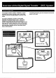
Overview of the Digital Signal Transfer ™ (DST) System Typ Configuration The concept for DIGITAL SIGNAL TRANSFER™ Stern The following illustration gives one rapier of how the DST originated from a desire 1o develop a way 1o easily enjoy system can be used, music or movie with a simple operation in any room of the house, The system is designed 1o provide you the greatest enjoyment with the least amount of work. it will not be necessary to remember complex steps of operation or controls.
Q Overview of the Digital Signal Transfer * (DST) System Understanding the DST System The DST system transmits up to 3 digital audio signals, 1 Transmitting audio signals digitally assures high quality analog audiovisual signal and remote control signals sound, without experiencing the type of degradation. through a 75-ohm coaxial cable*. This system consists of distortion or signal loss associated with conventional the following main equipment: hardware systems.
Overview of the Dig Signal Ti [CIRRHOSIS] Features of the DST system Multi-room and multiple source transmission « Simultaneous transmission of 3 digital audio sources plus the monaural audio signal of a video source The DST system transmits simultaneously 3 audio sources as well as 1 video source. Three audio sources are Transmitted digitally. Ons of the audio sources is input at 44.1 kHz. and the other audio sources are transmitted by first being converted from analog to digital.
Precautions « Operate the unit only on 120V Should any solid object or liquid fall into the cabinet, unplug the unit and have # checked by qualified personnel before operating it any further. » Unplug the unit from the wall outlet if it is not 1o be used for an extended period of time. To disconnect the cord, pull it out by grasping the plug. Never pull the cord itself. + Ona blade of the plug is wider than the other for the purpose of salty and will fit into the power outset only one way.
cation for Master Digital Control Center [2GTT fia (306409 Refer 1o the pages indicated for derails. (1 IR SENSOR Put the head of anther manufacturer's remote commander 10 program ifs resole control signal on this master digital control center. 34 Remote control sensor Pint the head of the RM-P Re mate Commander {supplied) here. (3} STANDBY indicator Blinks for about 10 seconds when the power of lhe system turns on, then goes off. Lights when the power of the system tuns off.
Refer o the pages indicated for details. (& VIDEO 3 input fracks Connect video equipment such as a video camera recorder. (i} VIDEO 2 button and indicator Press to select the program source connected to VIDEO 3 jacks. {# Programmable buttons for other manufacturers’ remote commander 33 RESET: Press if the remote control operation does not function.
Connections System Configuration Here is a typical system configuration.
[T + Do not remove any enclosure of the unit when « Be lore connection, be sure to limn off all equipment. connecting or installing the equipment. Refer « Inge rt the plug fully. Lose connection may cause the installation which requires opening of the unit to your noise. nearest Sony ES dealer. « To disconnect the cord, pull it out by the plug. Never pull + When any wiring of the 75-ohm coaxial cable is the cord itself. required, conduit your nearest Sony ES dealer.
Connecting the Signal Combiner and Digital Link ™ Decoder Amplifier When installing the MX: Locate a space large enough 1o accommodate the unit and accessible enough o connect the necessary coaxial cables, hot Be sure to complete installation before contenting the 75+ ohm coaxial cables. If the space selected is a wooden surface Use the four wood screws (652 in., /2 in, length). 1 Mark the mounting hole locations.
Up to four digital link rooms can be connected 1o the DST system, 75-chm coaxial cable {not supplied) F-type connector {supplied) Wall plate tor 76-ob coaxial cable* Typo 75-ohm coaxial cable connector {rot supplied) {not supplied) * it the room is not provided with a wall plate for a 75-ohm Wall plate for 75-ohm {supplied)* Wall plate for 76-ohm coaxial able, consult your nearest installer or Sony ES dealer, Coaxial cable™ Type connector __Digital Link™ Decoder Amplifier Wall plate for 75-chm inl cable* 75
Connecting the Signal Combiner and Digital Link™ Decoder Amplifier When Connecting More Than Four Di A splutter {not supplied) is required. The use ¢f four four-way splicers enables up 1o 18 digital link rooms 1o be connected to the ai Link ™ Decoder Amplifiers DST system.
Before Connection Before connection, you must attach an F-type colonnade to each end of the coaxial cable. Attaching the F-type connector (supplied) 1 Open the lid. > 2 Trip the cable. (D Strip 18 mm (®32 inch) of the black polyvinyl jacket. (@ Strip 10 mm ("3 inch) ol the white plastic leaving 10 mm of the center conductor. (D) Fold back the woven wire. Coming Loosen the screws and inert the cable. 4 Remove the ring. {Put it on the projection on the lid.} 5 Coil the center conductor.
Connecting a VCR, Tuner or TV Connect Eug ey When you connect 2 tuner in the master room, use a splutter {not supplied) as illustrated on the next page. RF signals can be transmitted in parallel to a VCR and tuner. : If you connect a TV as illustrated on the next page. you can watch CATV programs in the master room. Be sure to connect the TV 1o the MONITOR QUT jack of the master digital control center even in this case. (See page 22.
Master do'ta! control contra INPUT F-type connector 4, 1, x4 75.0hm of RF IN gfip""“ for B antenna input B splutter b ) 75-ohm coaxial RF OUT (not supplied) (nol supplied) VHF/UHF N VCR 78-ohm coaxial cable {supplied for the VCR) ™ How to attach the F-type connector (supplied/not supplied) See page 17. How to attach the EA-66 U/V band separator/mixer (not supplied) See the right column. Attaching the EA-66 U/V band separator/mixer (not supplied) 1 Loosen the screws on the U/V band mixer/separator.
Before Connecting Your Audio/Video Equipment to the Master Digital Control Center ure That Your Audio/Video Equipment Can Be Connected to the Master Digital Control Center Using to the following flow chart. first make sure that your audio/video equipment can be connected to the master digital control center, and proceed with connections. Yes Your audiometer equipment nosy product? 3 Equipped with a CONTROL § jack? Ne Yes Tno resemble contortionist an Yes page 22. Go to page 25.
Connecting Audio/Video Equipment “quipped with CONTROL S IN Jack FEE T E uu.ii, SEE DIGITAL QUT (OPTICAL) 10 VIDEO IN l 10 AUDIO OUT 5 TV equipped with a video input jack.
Connecting remote control cords o CONTROL S IN to CONTROL 8 QUT to CONTROL B IN VCR 1 o CONTROL SN VCR 2 or LD player H Notes * Be sure to connect the equipment which commands to the indication on the jack, I equipment other than that indicated is connected, the cremate control for that equipment does not function. + *When you connect a DAT deck without 2 CONTROL S IN jack, connect the DAT deck with cable having an LED emitter, (See page 25.
Connecting Audio/Video Equipment Connecting sure to connect the TV 1o the MONITOR OUT jack with a video connecting cord. Otherwise, you cannot watch a video playback picture on the TV. « When the control signal cord is connected as illustrated on page 23, you can control the DST system by pointing the RM-P Re mole Commander to the remote control sensor of the TV. Note that the remote control sensor of the master digital control center cannot receive control signals in this case.
Connecting audiovisual cords Refer to page 22, Connecting remote control cords Use & cable having an LED emitter for one end and a mini plug for the other end {not supplied). See the next page.
Connecting Audio/Video Equipment Attaching an LED emitter to the remote control sensor of your audio/video equipment Attach the LED emitter with opaque adhesive tape 30 that the eys of the LED emitter will be facing the remote control sensor, Be sure 1o cover the entire remote control sensor with opaque adhesive tape, Otherwise, your audiovisual equipment may receive the signal from the RM-P and malfunction, 26
Connecting a Power Amplifier or FM Receiver Connecting a Power Amplifier Other Than the QSR lvi ] Connect a power amplifier to fasten to sound from speakers. Connecting the TA-E1000ESD Amplifier When the control cord is connected as illustrated below, you can control the TA-E1000ESD by pointing the remote commander {(supplied for the TA-E1000ESD) at the remote contra sensor of the master digital control center. L-=J 1o PRE OUT] to LINEN F’orwetarnplifieflg.
Connecting a Power Amplifier or FM YENISEI Connecting an FM Receiver Equipped with CONTROL S IN and POWER IN Jacks When the control signal is connected as illustrated below, you can control the FM receiver by pointing the remote commander {supplied for the FM receiver) at the remote control sensor of the master digital control center. » When you use the FM receiver as a power amplifier only, make connection marked *.
to ADAPTER OUT | Jio ADAPTER IN—== 1o LINE LINE OUT Graphic equalizer Connect the AC power of all equipment except the followings: TV « VCR or LD player that can be turned on and off with remote control signal, Audiovisual equipment Notes + Be careful that the total power consumption of the equipment connected to AC OUTLET does not exceed 500 wails. + Do not connect electrical home appliances such as an electric iron or {an to these outsets.
(i1 TV operation buttons Mode selector: Set 1o SONY STD (standard) to operate a Sen TV. Set to USER STD to operate another manufacturer's TV after programming each signal to this Remote Commander. Set to LEARN to program the signals of the remote commander of another manufacturers TV, Program number (1 to 0) and ENTER buttons: Celesta TV channel. POWER ON and OFF buttons: Tums on and off the power of the TV.
Loading the Remote Three Blocks on the Commander with the Batteries Before operating the Remote Commander, install the batteries as illustrated. 1 Tyre size AA (R6) batteries When the batteries are run down The ¢XJ indication appears on the display window. Replace the batteries with new ones.
Audio/Video Equipment Operation Block Check the audiovisual equipment connected to the master digital control center, 1s your audiovisual equipment a Sony product? ] No No preparation is required. You need to program remote control signals on the master digital control center before using the RM-P Remote Commander. Refer to the next page.
Audio/Video Equipment Operation Block Control Signals on the Master Digital Control Center 4 Program the remote control signaler of another manufacturer's equipment, Example: When programming the » button of the VCR connected to the VIDEO 1 jack (D Place the supplied spacer as illustrated so that the IR SENSOR is covered. @ Press and hold the P button of the remote commander for the VCR. ® Attach the commander’s head to the IR SENSOR. Set the USER/LEARN selector fo LEARN.
TV Operation Block Check your TV, I is your TV a Sony product? Yes J{ Ne You need to program TV's resole control signals on the RM-P Emote Commander. Bo to page 37, Go to the right column. Programming 4] Normally, o begin video playback you must press VIDEO 1 or VIDEO 2 and then select the video input source or the channel for video, By programming the buttons the RM-P Remote Commander, you can start video playback with just one press of the VIDEO DIVIDE 2 button.
TV Operation Block How to program Sony TV's remote control signals on the RM-P Remote Commander 2 Program a signal. {D Cross and hold the button for which the remote control signal will be programmed, with a pointed object such as a ball-point pen, until “READY™ appears on the Display window of the RM-Pt.
nails on the RM-P Remote Commander Set the mode selector 1o LEARN. nosy usm D ST Lea 2 Program a signal. (D Press and hood the button for which the remote control signal will be programmed until “READY" appears on the display window of the RM-P, (D Press and hold the bunion of the other manufacturer's remote commander whose signal is to be programmed, ® Remove your finger(s) from the ablutions} after “OK" appears on the display window. [f “ERROR” appears, go back 10 step 2 (.
TV Operation Block To program a new signal onto a previously programmed button Follow the programming procedure. The previously programmed signal is cleared and replaced by the new signal. To clear all programmed signals 1 Set the mode selector to LEARN, 2 Press and doth CLEAR until "CLEAR" changes to “GLR OK” on the display window. Note Iris not possible o clear the programmed content of the just one button.
ony e s s ties Basic Operation You can select a program source among VIDEO 1, VIDEO 2, TV/AUX, TAPE 1, TAPE 2 {or DAT), and TUNER. g1 ETE R T) insert a cassette tape or a disc to be played back according To play a video tape in a digital link room to the program source. * When you use a Sony TV, program the buttons 1o be pressed for the setting of a TV onto the buttons Ato C of To play a video tape in the master room the RM-P Remote Commander, (See page 35.
Basic Operation Fo listen alchemist a different program source Press the desired function bunion. To turn off the power of the system Pres POWER OFF*. The indicator of the function will go out. * Automatic power oft The power of the DST system excluding TV will be turned off automatically 30 seconds after you pressed POWER OFF either in the master room or digital ink room unless other promise) are using another Program SOURCE.
Operation with Priority priority of the cremate control, When you have the priority, MR various operations are possible for the function appearing Available n on the display window, either in the master room iron a operation digital link room. Start playback with VIDEO 1, VIDEO 2 or . You want to Press Lop playback " See a sill picture (pause mods} | B CD‘ Function you control Release the pause mode Born e appears.
Operation with Priority Cassette Tape Operation Available operation Start playback with TAPE 1, TAPE 2 or b, Compact Disc Operation Available operation Start playback with You want o Press You want to Press Stop playback " Stop playback a Stop playback temporarily {paves mode} | 0 Stop playback temporarily (pause mode) | 1§ Ra lease the pause made Ao release the pause mode Hor Advance the gape rapidly > Locate a following selection ot Fond the tape ["Locate a previous selection e Change the playback side” L
About the Priority of Remote Control Purpose Ta avoid mixing up remote control signals, the DST system allows only ona room 1o control each program source. The room which has the “priority” can control that program source, What Is “priority? The PRIORITY indicator on the master digital control center or digital link touch panel lights if the room has the priority.
About the Multi-Room Operation In the DST system, several rooms are connected to the system and it is impossible to watch operations in other rooms. Unwanted operation may occur when you are playing a program source. This section explains the system of the multi-room operation and imaginable problems. L BRUTE LT 3 { The MASTER and LINK indicators on the master digital contort center allows you fo check what program source(s) is used in the DST system.
In the DST system, audiovisual signals to be transmitted simultaneously are limited as described below. When you want 1o select a different program source from the one played in the master room or other digital link rooms, note that up to five program sources Is available simultaneously.
Recording Note that you cannot perform recording — by using the RM-P Remote Commander. ~ on the Digital Link™ Touch Panel. » Insert a blank tape. disc or recorded tape into each « To record a TV program playback/recording equipment. Select a desired channel on the AM-Pt Remote Commander or TV. 1 Crass the function button to defect the desired program source. 2 I the PRIORITY indicator on the front panel does not fight. press PRIORITY on the RM-Pt Remote Commander to obtain the priority.
Optional et 14 The DST system can be expanded with the use of optional accessories other than the supplied ones. Refer fo the {hollowing optional accessories for system expand ability. For audio, video and control cords, refer to page 21.
Specifications Amplifier Section Frequency response kHz 20.1d8 Input sensitivity 150 mV, 50 idiot tums SN 90 98 Output voltage and output impedance REC OUT: 150 mV, 470 ohms. PRE QUT: 1.3V, 50 ohms {(nominal) HEADPHONES: 15 mV, 8 ohms; accepts low and high impedance headphones Total harmonic distortion Lass than 0.015 % Video Section Frequency response MHz. Video input sensitivity and input impedance 1Vpp. 75 ohms. Video output voltage and output impedance 1 VP-p. 75 ohms.
Troubleshooting Be tore proceeding through the check list below, examine the connections and the procedures outlined in this operating instructions. Should any problem persist after you have checked the following miles, consult your nearest Sony ES dealer. L Room Operation # you cannot locate your problem in this chart, go to "System Operation,” Sound Problem Cause Solution No sound is heard even if the volume is. The parer amplifier, speaker, or program Connect the equipment correctly. {See adjusted.
Troubleshooting Compact Disc operation ape operation does not function correctly with the RM-P Remote Commander. Commander is sel 1o the one you do not control, Proteins Cause Solution €D 1 cannot bs selected. Your CD player has not a parallel culprit of Use a CD player with a parallel output of digitization signals, and digital link room digitization signals for CO 1. {Ceausescu 1.
Remote control operation Problem Cause Solution The BM-Pa Remote Commander doss not + Tha batteries are exhausted. Replace the bangles with new ones, function. + The commander head is not pointed Point the commander bead toward the sward the remote control sensor. senior. « Thea is an object between the RM-P Remote Commander and the equipment you control. Remove the object.
Troubleshooting stem Operation Problem Cause Solution Both of the master digital control center ang 1he digital link decoder amplifier function incorrectly. + They are connected incompletely. Check the connection and connect each piece of equipment correctly. (See pages 1510 18.) » More than 16 digital link decoder amplifiers | Connect only 16 digital fink decoder are connected. amplifiers. + The same room number is assigned to Check the ROOM NUMBER selector on 1w digital link decoder amplifiers or more.