2-676-745-31(1) AIT Drive User’s Guide AIT-3 Ex TAPE DRIVE SDX-800V Series 2006 Sony Corporation
This document contains proprietary information which is protected by copyright. All rights reserved. No part of this document may be photocopied, reproduced or translated to another language without prior written consent of Sony. The information contained in this document is subject to change without notice. SONY MAKES NO WARRANTY OF ANY KIND WITH REGARD TO THIS DOCUMENT.
IMPORTANT SAFEGUARDS USE For your protection, please read these safety instructions completely before operating the appliance, and keep this manual for future reference. Power Sources – This unit should be operated only from the type of power source indicated on the marking label. If you are not sure of the type of electrical power, consult your dealer or local power company.
INSTALLATION SERVICE Water and Moisture – Do not use power-line operated units near water – for example, near a bathtub, washbowl, kitchen sink, or laundry tub, in a wet basement, or near a swimming pool, etc.
Table of Contents Overview .................................................................................................................. 6 Introduction .............................................................................................................. 7 About AIT Drives ............................................................................................ 7 Precautions .......................................................................................................
Overview The Sony SDX-800V series drives are high capacity data storage devices using Advanced Intelligent tape (AIT) technology. The SDX-800V series drives achieve high data reliability through Read-After-Write, an additional level of Error Correction Code, and other features. The Sony SDX-800V series drives store data on tape using standard formats called AIT (Advanced Intelligent Tape) and ALDC.
Introduction About AIT Drives SDX-800V series drives are internal AIT drive units that use data cartridges conforming to the AIT-3 Ex format. SDX-800V series drives support AIT-1, AIT-2, AIT-3 and AIT-3 Ex formats. Features The SDX-800V series drives have the following features: • Support reading and writing to data cartridges conforming to the AIT-3 and AIT-3 Ex formats. • Supports reading to data cartridges conforming to the AIT-1 and AIT-2 formats.
Precautions Useable Cartridges SDX-800V series can be used with data cartridges marked with the AIT-1*, AIT-2*, AIT-3 or AIT-3 Ex logo. * Read only Notes • Be sure to use only data cartridges designed specifically for AIT (do not use 8 mm video cartridges) as this may damage the drives. • Do not use anything but AIT cartridges with this system, as doing so can damage the AIT drive.
Transportation • Keep the original packing materials to facilitate safe transportation of the drives. • Always remove the tape/media cartridge before moving the drives. After removing the drives from the computer, repack them into their original packing. SCSI Termination The SDX-800V series drives conform to the Microsoft PC97 standard, which requires the internal (naked) drive to be terminated with an external terminator. Microsoft PC97 SCSI requirements SCSI peripherals must not terminate the bus.
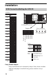
Installation SCSI Connection/Setting the SCSI ID SCSI ID P.D. N.C. 3 2 1 0 SCSI ID 0 1 2 SCSI 68pin Connector 3 Jumpers 4 Power Connector 4 3 2 1 5 5 V GND GND 12 V Parity Disable No Connection SCSI ID 3 SCSI ID 2 SCSI ID 1 SCSI ID 0 6 7 8 9 Parity 10 Disable 11 Enable 12 Note : 13 = CLOSED/Jumper = OPEN/Jumper not installed 14 = Don’t care 15 Parity Disable Jumper Parity check function can be disabled by Jumper. Parity check is disabled while left end jumper is installed.
Option Switches (DIP Switch) DIP Switch DIP Switch Positions Default ON OFF 1 2 3 4 5 6 7 8 1 2 3 4 5 6 7 8 DR (Disaster Recovery) Mode (OFF) Emulation Mode (OFF) AIT Library Interface Mode (ON) Reserved (OFF) Terminator Power (ON) Periodic Cleaning Req (ON) DC Control (1) (ON) DC Control (2) (OFF) 11
DR (Disaster Recovery*) Mode To enable DR Mode, set position 1 [Drive Mode] switch to ON. ON OFF 1 * 2 3 4 5 6 7 8 1 2 3 4 5 6 7 8 DR (Disaster Recovery) Mode (ON) Emulation Mode AIT Library Interface Mode Reserved Terminator Power Periodic Cleaning Req DC Control (1) DC Control (2) In Disaster Recovery Mode, an SDX-800V series drive enters the DR Standby Mode 15 seconds after you insert a write-protected tape into the drive, and all the drive LED blink.
Library Mode The Library Mode can be enabled with a DIP switch. ON OFF 1 2 3 4 5 6 7 8 1 2 3 4 5 6 7 8 DR (Disaster Recovery) Mode Emulation Mode AIT Library Interface Mode (ON) Reserved Terminator Power Periodic Cleaning Req DC Control (1) DC Control (2) When switch 3 is ON, AIT-1, 2, 3 compatible Library Mode is enabled. With this switch OFF, ACI Mode is enabled. Terminator Power Control DIP switch This DIP switch determines whether terminator power is supplied to the SCSI bus.
_ 0.5mm 9.9 + _ 0.02"] [0.39" + _ 0.5mm 21.8 + _ 0.02"] [0.86" + _ 0.5mm 41.2 + _ 0.02"] [1.62" + _ 0.3mm [1.22" + _ 0.01"] 31.0 + _ 0.5mm [6.10"+ _ 0.02"] 155.0 + _ 0.3mm 47.5 + _ 0.01"] [1.87"+ _ 0.3mm [3.12"+ _ 0.01"] 79.2 + _ 0.3mm 42.0 + _ 0.01"] [1.65"+ _ 0.3mm [2.76" + _ 0.01"] 70.0 + _ 0.6 mm 9.8 + _ 0.02"] [0.39" + _ 0.3mm 21.0+ _ 0.01"] [0.83"+ _ 0.5mm 41.2 + _ 0.02"] [1.62" + _ 0.6 mm 9.8 + _ 0.02"] [0.39"+ _ 0.3mm [3.12" + _ 0.01"] 79.2 + 7.0mm [0.28"] _ 0.5mm 4.8 + _ 0.
Reconfiguring from 5.25" Model to 3.5" Model You can reconfigure the 5.25" model to the 3.5" model yourself. 1 Remove the 2 screws for each side rail. 2 Take the side rail off.
Orientation 10 10 10 10 10 10 10 10 16
Attaching and Removing the Dust Cover Attaching the Dust Cover 1 Align the dust cover’s hinge clips (one on each side) with the pins of the drive bezel. • The dust cover should be positioned so that the magnets* on the cover’s back face the drive bezel. * • This magnet does not affect the tape of the cartridge. Holding the dust cover at an angle, as shown in the figure below, set the hinge clips on top of the bezel pins, positioning them so that they bracket the pins.
2 Press down at an angle on each side in turn until you hear the hinge clips click into place. Caution Do not press the dust cover in horizontally from the front. Doing so could cause the dust cover to break. 3 Close the dust cover. This completes attachment of the dust cover.
Removing the Dust Cover 1 Open the dust cover. 2 Holding the dust cover at both corners, carefully raise the dust cover. The dust cover hinge clips and drive bezel pins uncouple. Note We recommend that you use the drive with the dust cover.
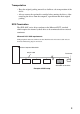
Operation Location of 3 LEDs There are three LED indicatiors (TAPE MOTION LED, CLEANING REQUEST LED, REPLACE TAPE LED) and an EJECT button on the front panel of the SDX-800V series drives.
Drive Operation Loading a Cartridge Note While setting the data cartridge, do not turn off the host computer. This may cause a malfunction or damage data. 1 Turn on the host computer. Check that the drive’s TAPE MOTION LED, CLEANING REQUEST LED and REPLACE TAPE LED go off. 2 Open the dust cover. 3 Set the AIT data cartridge orientation as shown here and insert it into the data cartridge slot. By fully inserting the data cartridge, it is automatically set in the drive and the TAPE MOTION LED lights.
Unloading a Cartridge The cartridge can be removed from SDX-800V series drives in response to a SCSI Unload command, or by pressing the EJECT button. When the EJECT button is pressed, the tape is rewound and the cartridge ejected from the slot. Write-protecting a Cartridge Cartridges can be write-protected by sliding the tab on the back of the cartridge. In this state, data can be read from the tape but not written onto it.
How to Clean 1 Load the cleaning cartridge (SDX3X-CL) into the SDX-800V. Cleaning starts automatically. 2 Cleaning takes from a few seconds to a minute for the SDX800V,*1 and the cartridge is automatically ejected when finished. *1 The cleaning time varies depending on the condition of the drive. Caution Do not rewind the cleaning cartridge and reuse it. When you reach the end of the cartridge, dispose it and buy a new cleaning cartridge with the AIT logo.
Emergency Tape Removal Procedure 1 Remove the drive from the chassis or enclosure to allow access to the bottom of the drive. 2 Remove the drive’s top cover. 3 Locate the small opening in the bottom of the drive and insert the tip of a precision screwdriver so that the Loading motor shaft can be rotated. 4 Rotate the motor shaft clockwise to bring the threading mechanism back to the initial position.
Caution Stop rotating the motor shaft immediately, when the guide B gets to the area below the line C-C (This line is defined by 2 circular tape guide surfaces of the cartridge). Otherwise, the gears of the drive can be damaged. A Tape guide surface Tape guide surface C C detail A B Cartridge The Initial Position of the Threading Mechanism 5 Before the manual ejection procedure, tape slack must be removed in order to prevent tape damage.
Interface Implementation Supported SCSI Messages Abort Identify Target Reset Ignore Wide Residue Command Complete Message Parity Error Disconnect Message Reject Extended Message No Operation – Synchronous Data Transfer Request – Wide Data Transfer Request – Parallel Protocol Request Supported SCSI Commands 26 Erase Release (6) Inquiry Release (10) Load/Unload Report Density Support Locate Report Device Identifier Log Sense Report Luns Log Select Request Sense Mode Select Reserve (6
Specifications Product Specifications Dimensions (not including bezel and protruding parts) 3.5" 41.2 mm (1.62 in) 101.6 mm (4.0 in) 155.0 mm (6.1 in) Height Width Depth 5.25" 41.2 mm (1.62 in) 146.0 mm (5.75 in) 155.0 mm (6.1 in) Mass 3.5" 5.25" 780 g (27.5 oz.) 1010 g (35.6 oz.) Altitude Operating 0 to 3048 m (0 to 10,000 ft.) Vibration Operating Non-operating Swept Sine 5 to 500 Hz *0.25 G Peak 1 Octave/min. 3 axes, 3 directions Swept Sine 5 to 500 Hz *0.5 G Peak 1 Octave/min.
Shock Operating Non-operating No Data Loss Half Sine Performance 5 G Peak 3 ms 3 axes, 3 directions *Interval of 10 seconds No Device Damage Half Sine 90 G Peak 3 ms (30 G Peak 11 ms) 3 axes, 3 directions *Interval of 10 seconds Temperature and Humidity Range Temperature Operating Non-operating (mech.
Sony Contacts For further information, please contact the appropriate Sony location listed below: Sony Electronics Inc., Tape Storage Solutions (USA) URL: http://www.storagebysony.com Sony of Canada Ltd., AV/IT Marketing Group Computer Peripherals Product Marketing 115 Gordon Baker Road Toronto, Ontario, M2H 3R6 Canada TEL: (416) 499-1414 or (1) 800-961-7669 FAX: (416) 499-8541 Sony Business Europe URL: http://www.sonyisstorage.
Sony Brasil Ltda. Rua Inocéncio Tobias, 125, Barra Funda São Paulo-SP, Brasil 01144-000 TEL: (55) 11-2196-9000 FAX: (55) 11-2196-9186 URL: http://www.sonybrasil.com.br Sony Australia Limited 33-39 Talavera Rd. NORTH RYDE, NSW 2113 TEL: 1300-13-7669 FAX: 02-9870-5864 e-mail: CIC-customerissues@ap.sony.com Sony New Zealand Akoranga Business Park NORTH SHORE, AUCKLAND TEL: 0800-76-6969 FAX: 09-308-9300 e-mail: CIC-customerissues@ap.sony.com Sony Chile Ltda Av.
Printed in U.S.A.