DSC-S600 SERVICE MANUAL LEVEL 2 US Model Canadian Model AEP Model UK Model E Model Australian Model Chinese Model Brazilian Model Hong Kong Model Korea Model Ver 1.0 2005.
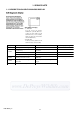
These specifications are extracted from instruction manual of DSC-S600 (2-658-425-11). SPECIFICATIONS Camera [Power, general] Power [System] Image device 7.18 mm (1/2.5 type) color CCD, Primary color filter Total pixel number of camera Approx. 6 183 000 pixels Effective pixel number of camera Approx. 6 003 000 pixels Lens Carl Zeiss Vario-Tessar 3 zoom lens f = 5.1 – 15.3 mm (31 – 93 mm when converted to a 35 mm still camera) F2.8 – 5.
SAFETY CHECK-OUT After correcting the original service problem, perform the following safety checks before releasing the set to the customer. 1. 2. 3. 4. 5. 6. Check the area of your repair for unsoldered or poorly-soldered connections. Check the entire board surface for solder splashes and bridges. Check the interboard wiring to ensure that no wires are "pinched" or contact high-wattage resistors.
TABLE OF CONTENTS 1. SERVICE NOTE 1-1. DESCRIPTION ON SELF-DIAGNOSIS DISPLAY ······ 1-1 1-2. METHOD FOR COPYING OR ERASING THE DATA IN INTERNAL MEMORY ·················································· 1-2 1-3. PRECAUTION ON REPLACING THE SY-145 BOARD ··········································································· 1-3 1-4. INITIAL LANGUAGE DATA CHECK ·························· 1-3 1-5.
1. SERVICE NOTE 1-1. DESCRIPTION ON SELF-DIAGNOSIS DISPLAY Self-diagnosis display • C: ss: ss You can reverse the camera malfunction yourself. (However, contact your Sony dealer or local authorized Sony service facility when you cannot recover from the camera malfunction.) • E: ss: ss Contact your Sony dealer or local authorized Sony service facility. Display Code C:32:ss Countermeasure Cause Caution Display During Error Turn the power off and on again. Trouble with hardware.
1-2. METHOD FOR COPYING OR ERASING THE DATA IN INTERNAL MEMORY The data can be copied/erased by the operations on the Setup screen. (When erasing the data, execute formatting the internal memory.) Note1: When replacing the SY-145 board, erase the data in internal memory of the board before replacement. Note2: When replacing the SY-145 board or the IC203 on the SY-145 board, execute formatting and initialize the internal memory after replacement.
1-3. PRECAUTION ON REPLACING THE SY-145 BOARD • The Repair Board has already been adjusted. Re-initialization or EVR data copy from the set before repair is not required. • Perform “Initial Language Data Check” mentioned below, and also the adjustment items necessary after SY Board replacement. 1-4. INITIAL LANGUAGE DATA CHECK If the SY-145 board was replaced, initial language setting may be changed.
2.
2. DISASSEMBLY 2. DISASSEMBLY NOTE FOR REPAIR Make sure that the flat cable and flexible board are not cracked of bent at the terminal. Do not insert the cable insufficiently nor crookedly. When remove a connector, don't pull at wire of connector. Be in danger of the snapping of a wire. When installing a connector, don't press down at wire of connector. Be in danger of the snapping of a wire. Cut and remove the part of gilt which comes off at the point.
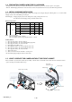
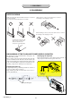
-1 45 DSC-S600_L2 2-3 4 Cabinet (upper) assembly 3 LCD unit 1 Screw (M1.7x4) SY 3 RL-063 board 3 2 4 8 Cabinet (rear) assembly 4 Screw (M1.7x4) 4 B (See page 2-5) A (See page 2-5) 7 Open the cabinet (upper) assembly. 1 6 Screw (M1.7x4) 3 3 Open the USB cover. 7 6 HELP 01 5 Screw (M1.7x4) 5 8 2 Screw (M1.7x4) 2 Flexible board (from the LCD unit) 1 2 Two claws 3 2 1 2 1 Two solderings HELP 04 2-1. DISASSEMBLY 1 SY 2. DISASSEMBLY 1 Slide the BT cover. 2.
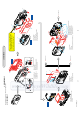
4 3 2-5 4 Lens block assembly, optical unit. 3 Flexible board (from the optical unit) 4 6 4 Two solderings 5 Miclophone holder 6 Miclophone 2 Speaker holder 3 Speaker S 1 Two solderings 1 HELP 05 Y 2 Flexible board (from the lens block assembly) 2 3 5 5 1 Flexible board (from the lens block assembly) 45 -1 SY 5 SW-461 board, flexible flat cable (FFC-058) 4 LCD frame 3 Screw (M1.
HELP Disassembling and assembling procedures that require attention are described here. HELP 01 When installing the Cabinet (Rear) assembly, install it while aligning the Mode switch of the SW-461 board with the position A of the Cabinet (Rear) assembly. Mode Switch of the SW-461 board Cabinet (rear) assembly A HELP 02 Solder each lead according to the color (Y: yellow, G: gray, W: white, R: red, B: black) displayed on the SW-461 board.
HELP 03 SY -1 45 When installing the cabinet (front) asembly, put the lead lines in the space between the tripod screw and the SW-461 board. When installing the cabinet (front) asembly, put the lead lines in the space between the optical unit and the DC mortor. SW-461 board Optical unit Tripod screw DC mortor HELP 04 Solder each lead according to the color (R: red, B: black) displayed on the SY-145 board.
HELP 05 Solder each lead according to the color (R: red, B: black) displayed on the SY-145 board. Mic unit Red Black SY-145 board Speaker HELP 06 Give folding to the flexible flat cable (FFC-057).
3.
3. BLOCK DIAGRAMS ( ) : Number in parenthesis ( ) indicates the division number of schematic diagram where the component is located. 3-1. OVERALL BLOCK DIAGRAM FFC-056 (FLEXIBLE FLAT CABLE) (2/3) CCD IMAGER and CD-606 FLEXIBLE BOARD are included in the LENS BLOCK ASSY (A-1156-857-A). LENS UNIT (LSV-951A) CD-606 FLEXIBLE BOARD X102 33.75MHz SY-145 BOARD IRIS SHUTER CCD IMAGER S/H A/D CONV.
( ) : Number in parenthesis ( ) indicates the division number of schematic diagram where the component is located. 3-2. POWER BLOCK DIAGRAM SY-145 BOARD D901 (RECT) T901 BATT UNREG BATTERY HOLDER F001 ST UNREG ST UNREG L901 15 STRB CHG 6 M5V F002 DC/DC CONVERTER REAL TIME CLOCK EVER 2.8V J1 UNREG1-1,2 K1 LDO1 H1 3.1V REG D001 R002 VL 3V VL 3V R22 X001 32.
4. PRINTED WIRING BOARDS AND SCHEMATIC DIAGRAMS 4-1. FRAME SCHEMATIC DIAGRAM 2 1 4 3 5 6 8 7 9 10 11 12 13 15 14 16 RL-063 BOARD 1 1 N.C. N.C. XPWR_ON XPWR_LED 2 2 XPWR_ON D_3.2V REG_GND XSHUTTER_SW 3 3 XPWR_LED XAE_LOCK_SW 4 4 D_3.2V XAF_LED 5 5 REG_GND N.C. 6 XSHUTTER_SW 9P B 6 7 7 8 8 9 N.C. XAF_LED XAE_LOCK_SW BATTERY HOLDER 9 A FFC-057 CN301 9P BATT_UNREG BATT_GND C LND001 LND002 FLEXIBLE FLAT CABLE CN1001 33 33P CAM-7.
4-2.
4-2. SCHEMATIC DIAGRAMS 4-2. SCHEMATIC DIAGRAMS THIS NOTE IS COMMON FOR SCHEMATIC DIAGRAMS (In addition to this, the necessary note is printed in each block) (For schematic diagrams) • All capacitors are in µF unless otherwise noted. pF : µ Link µF. 50 V or less are not indicated except for electrolytics and tantalums. • Chip resistors are 1/10 W unless otherwise noted. kΩ=1000 Ω, MΩ=1000 kΩ. • Caution when replacing chip parts. New parts must be attached after removal of chip.
4-2. SCHEMATIC DIAGRAMS 2 1 3 4 5 3 4 5 RL-063 BOARD BM-001 BOARD LENS OPEN/CLOSW MOTOR A 2 1 A XX MARK:NO MOUNT POWER SWITCH XX MARK:NO MOUNT S202 2 1 4 3 POWER 9P HN-011 HARNESS TO SW-461 BOARD LND401 LND403 LENSV_CLOSE HN-010 HARNESS LENSV_CLOSE LND402 LND404 LENSV_OPEN LENSV_OPEN + M – (PAGE 4-7) B M001 LENS BARRIER MOTOR B 16 TO SY-145 BOARD(7/8) THROUGH THE FFC-057 FLEXIBLE FLAT CABLE (PAGE 4-21 of LEVEL3) N.C.
• Refer to page 4-3 for mark 0. 2 1 3 4 5 6 7 8 9 10 SW-461 BOARD JACK,FUNCTION SW,LITHIUM BATTERY A 5P XX MARK:NO MOUNT 2 3 GND 4 VCC 5 VL_3V 6 7 XACCESS_LED 8 D_3.
4-3.
4-3. PRINTED WIRING BOARDS 4-3. PRINTED WIRING BOARDS THIS NOTE IS COMMON FOR WIRING BOARDS (In addition to this, the necessary note is printed in each block) (For printed wiring boards) • : Uses unleaded solder. • : Pattern from the side which enables seeing. (The other layers’ patterns are not indicated) • Through hole is omitted. • Circled numbers refer to waveforms. • There are a few cases that the part printed on diagram isn’t mounted in this model. • C: panel designation • Chip parts.
4-3. PRINTED WIRING BOARDS BM-001 (2 layers), LB-117 (2 layers), RL-063 (2 layers) • : Uses unleaded solder.
SW-461 (2 layers) : Uses unleaded solder. • SW-461 BOARD(SIDE A) MOVIE-STILL-PLAY 26 1 FB005 C001 8 10 CN006 9 S011 7 1 6 FB004 FB003 FB001 R001 R008 FB002 CAUTION : Danger of explosion if battery is incorrectly replaced. Replace only with the same or equivalent type.
4-3. PRINTED WIRING BOARDS no mark : side A * mark : side B 4-5.
NOTE 5. REPAIR PARTS LIST NOTE: Characters A to Z of the electrical parts list indicate location of exploded views in which the desired part is shown.
5. REPAIR PARTS LIST 5. REPAIR PARTS LIST NOTE: • -XX, -X mean standardized parts, so they may have some differences from When indicating parts by reference number, the original one. please include the board name. • Items marked “*” are not stocked since they are seldom required for routine The components identified by mark 0 or service. Some delay should be anticipated when ordering these items. dotted line with mark 0 are critical for safety.
5. REPAIR PARTS LIST 5-1. EXPLODED VIEWS 5-1-1. OVERALL SECTION 15 ns : not supplied 6 13 8 D 14 M001 C 12 ns E 9 ns 10 A 7 11 8 5 3 B 4 1 1 C B ns SY -1 45 D E 1 A 2 1 Battery holder section (See page 5-4) Ref. No. Part No. Description 1 2 3 4 5 2-599-475-31 2-660-555-01 X-2103-127-1 2-660-525-01 2-660-556-01 SCREW (M1.
5. REPAIR PARTS LIST 5-1-2. BATTERY HOLDER SECTION MIC901 65 64 52 ns : not supplied D 66 51 (15mm × 5mm) 67 55 78 A C9001 77 53 G 54 C E 51 ns (15mm × 5mm) 62 61 60 69 58 D SY (5.5mm × 5.5mm) (24mm : BLACK) X001 59 -1 45 68 (24mm : RED) H 56 E SP901 72 70 (39mm : BLACK) F LCD901 74 F 71 (39mm : RED) B A 75 B 77 57 C BT001 73 58 (5.5mm × 5.5mm) 60 : BT001 (Lithium battery) SW-461 board on the mount position.
5. REPAIR PARTS LIST Checking supplied accessories. Make sure that the following accessories are supplied with your camcorder.
BM-001 LB-117 RL-063 SW-461 SY-145 5-2. ELECTRICAL PARTS LIST Ref. No. Part No. Description Ref. No. FB006 FB007 A-1159-170-A BM-001 BOARD, COMPLETE *********************** ************************************************************ Part No.