
User's Manual

DSC-S600_L2
2-3 2-4
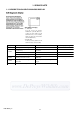
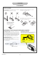
2-1. DISASSEMBLY
The following flow chart shows the disassembly procedure.
2. DISASSEMBLY
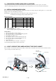
2. DISASSEMBLY
2. DISASSEMBLY
SY-145
SY-145
SY-145
SY-145
5
7
6
2
3
4
1
2
3
5
1
8
4
3
2
1
1
Slide the BT cover.
2
Screw (M1.7x4)
3
Open the USB cover.
4
Screw (M1.7x4)
5
Screw (M1.7x4)
6
Screw (M1.7x4)
7
Open the cabinet (upper) assembly.
8
Cabinet (rear) assembly
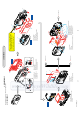
1
Three solderings
2
Two solderings
3
Open the BT cover.
4
Open the cabinet (upper) assembly.
5
Cabinet (front) assembly
1
Two solderings
2
Flexible board (from the LCD unit)
3
LCD unit
1
Two solderings
2
Claw
3
Two claws
4
Flexible board (from the lens block assembly)
5
Flexible board (from the lens block assembly)
6
Flexible flat cable (FFC-058)
7
Flexible flat cable (FFC-056)
8
SY-145 board, RL-063 board,
speaker, microphone, etc.
1
4
3
2
1
Screw (M1.7x4)
2
Two claws
3
RL-063 board
4
Cabinet (upper) assembly
1
2
8
3
5
6
4
A
(See page 2-5)
C
(See page 2-5)
B
(See page 2-5)
7
Refer to page 2-1 "DISCHARGING OF
THE FLASHLIGHT POWER SUPPLY
CAPACITOR (LND904, LND905)",
when discharging the capacitor.
HELP 02
HELP 01
HELP 03
HELP 04