DIGITAL HD VIDEOCASSETTE RECORDER HVR-1500 HVR-1500A DIGITAL VIDEOCASSETTE RECORDER DIGITAL VIDEOCASSETTE PLAYER DSR-60/60P DSR-1600/1600P DSR-1600A/1600AP VIDEO DISK RECORDER DSR-70/70P DSR-DR1000/DR1000P DSR-70A/70AP DSR-DR1000A/DR1000AP DSR-80/80P DSR-85/85P DSR-1500/1500P DSR-1500A/1500AP DSR-1800/1800P DSR-1800A/1800AP DSR-2000/2000P DSR-2000A/2000AP PROTOCOL MANUAL 1st Edition (Revised 8)
COPYRIGHT NOTICE Copyright © by Sony Corporation. All rights reserved. The copyright on all matters described in this manual belongs to Sony Corporation, and the contents are intended for use by purchasers of subject equipment. Furthermore, Sony Corporation reserves the right to revise this publication and to make changes from time to time in the content hereof without obligation of Sony Corporation to notify any person or organization of such revision or changes.
Table of Contents 1. Summary ................................................... 1 2. Interface System Overview ...................... 1 3. Command Block Format (CMD Block) .... 2 3-1. VTP Command .................................................................. 2 3-2. DSR-DR1000/A DISK Command ..................................... 3 4. Connector Pin Assignment ..................... 7 5. Communication Protocol ......................... 8 6. Command ..................................................
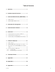
1. Summary The DSR series VTR, Remote Control Connector Panel, incorporate with a 9-pin D-Subminiature connectors for REMOTE. This connector is utilized for a serial control system. The definition of CONTROLLER and DEVICE is shown in the follows, “CONTROLLER” means the unit which controls VTR. “DEVICE” means the unit (VTR) which is controlled. Example 1) When the DSR series VTR is connected by REMOTE (9-pin) connector, the VTR as the recorder means CONTROLLER and the VTR as the player means DEVICE.
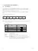
3. Command Block Format (CMD Block) 3-1. VTP Command The communication between the CONTROLLER and the DEVICE is composed of CMD-1 + DATA COUNT, CMD-2 + DATA and CHECKSUM, and is transmitted from CMD-1 + DATA COUNT in order. When the DATA COUNT is zero, the DATA is not transmitted. When it is not zero, the DATA corresponded with the value is inserted between CMD-2 and CHECKSUM. The command block can be illustrated as shown. MSD LSD CMD-1 DATA COUNT 1 BYTE CMD-2 DATA-1 DATA-n (MAX.
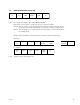
3-2. DSR-DR1000/A DISK Command ID DC CMD1 CMD2 DATA CS 1byte 1byte 1byte 1byte 0 to 255byte 1byte a. ID : Code undefined as CMD1 of Sony VTR 9PIN PROTOCOL. 0x30 and 0x31 are designated as an ID of the extension command for DISK. ID:0x30 : Indicates that it is a single block with less than 256-byte DATA length. Or it indicates that it is the last block when transmitting a command by dividing into multiple blocks.
c. CMD1: Specifies the categories of commands.
[System related commands] 0x00 to 0x07 are the ones that the upper four bits of CMD1 of the Sony VTR 9PIN PROTOCOL is shifted to four bits rightward. The content is the same as that of the Sony VTR 9PIN PROTOCOL. 0x10 to 0x12 are in a category related to parameter settings and requests unique to the device. [Drive related commands] 0x13 to 0x15 are in a category related to controls or parameter settings and requests for the DISK DEVICE that the device has.
d. CMD2 : Assigns individual commands according to the following code category list. .
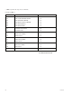
4. Connector Pin Assignment Interface connector : 9 pin D-subminiature female (D-9S) The pin assignment for the CONTROLLER and the DEVICE is as shown in the following table. Among the DSR series VTRs, the VTRs (DSR-85/85P) that have the built-in CONTROLLER function, obtain the following CONTROLLER pin assignment when they execute the QSDI dubbing and also when the RECORDER lamp or the PLAYER lamp turns on the control panel. Except for that, it’s become pin assignment of DEVICE.
5. Communication Protocol 1) All communication between the CONTROLLER and the DEVICE will be under the direct supervision of the CONTROLLER. When the DEVICE receives the COMMAND sent from CONTROLLER, the following COMMAND is returned. . In the case that the DEVICE receives the COMMAND not required the data ..................... ACK . In the case that the DEVICE receives the COMMAND required the data ..................... COMMAND + DATA .
6. Command The marks shown in the tables mean the following contents. 1) O marked COMMAND’s model can correspond. If the contents are in the RETURN column, RETURN + DATA will be returned. If the contents are not in the RETURN column, “10.01 : ACK” will be returned. 2) T marked COMMAND returns ACK as RETURN, but does not operate. 3) X marked COMMAND does not correspond and returns “11.12.01 : NAK UNDEFINED COMMAND.
DSR-2000/A DSR-1800/A DSR-1600/A DSR-1500/A DSR-85/80 DSR-70A DSR-70 DSR-60 HVR-1500/A (DVCAM) HVR-1500 (HDV) HVR-1500A (HDV) 20.42 : AUTO EDIT O T T O O T O O O O T 20.4B : DMC RUN X X X O X X X X O X X 20.4C : DMC PREVIEW X X X O X X X X O X X 20.52 : TENSION RELEASE O O O O O O O O O O O Command Return 20.54 : ANTI-CLOG TIMER DISABLE O/T → ACK O O O O O O O O O O O 20.
DSR-2000/A DSR-1800/A DSR-1600/A DSR-1500/A DSR-85/80 DSR-70A DSR-70 DSR-60 HVR-1500/A (DVCAM) HVR-1500 (HDV) HVR-1500A (HDV) 44.00 : TIMER-1 PRESET O O O O O O O O O O O 44.04 : TIME CODE PRESET O O O O O T O O O O T 4X.05 : USER’S BIT PRESET O O O O O T O O O O T 40.08 : TIMER-1 RESET O O O O O O O O O O O 40.10 : IN ENTRY O O O O O O O O O O O 40.11 : OUT ENTRY O O O O O O O O O O O 40.
DSR-60 X DSR-70 X DSR-70A O DSR-85/80 X DSR-1500/A DSR-1600/A X DSR-1800/A X 40.46 : VARIABLE MEMORY OFF DSR-2000/A Return HVR-1500/A (DVCAM) HVR-1500 (HDV) HVR-1500A (HDV) Command X X T X X 40.47 : VARIABLE MEMORY ON X X X O X X X X T X X 42.50 : DA INPUT SELECT O O O O O T O O O O T 4X.54 : EXTENDED DA INPUT SELECT O O O O O T O O O O T 41.58 : DA SAMPLING FREQ PRESET O T T O O T O O O O T 41.
DSR-2000/A DSR-1800/A DSR-1600/A DSR-1500/A DSR-85/80 DSR-70A DSR-70 DSR-60 HVR-1500/A (DVCAM) HVR-1500 (HDV) HVR-1500A (HDV) 74.08 : GEN TIME DATA O O O O O X O O O O X 74.09 : GEN UB DATA O O O O O X O O O O X 78.08 : GEN TC & UB DATA O O O O O X O O O O X 74.00 : TIMER-1 DATA O O O O O O O O O O O 74.01 : TIMER-2 DATA O O O O O O O O O O O 74.04 : LTC TIME DATA O O O O O O O O O O O 78.
DSR-2000/A DSR-1800/A DSR-1600/A DSR-1500/A DSR-85/80 DSR-70A DSR-70 DSR-60 HVR-1500/A (DVCAM) HVR-1500 (HDV) HVR-1500A (HDV) 60.70 : VIDEO INPUT SENSE 72.70 : VIDEO INPUT STATUS O O O O O X O O O O X 60.9E : SUPERIMPOSE SENSE 71.9E : SUPERIMPOSE STATUS O O O O O O O O O O O 60.AE : AUDIO MONITOR 74.AE : AUDIO MONITOR CHANNEL STATUS O O O O O O O X O X X 60.C2 : TIMELINE SOURCE SENSE 71.C2 : TIMELINE SOURCE O O O O O O O O O O O 60.
6-2. Command Table (for Disk Recorder) “IN (R)” of DSR-DR1000/A indicates the RECORDER side during the simultaneous record/playback (REMOTE I/F of INTERFACE SELECT is set to “9PIN (DUAL))”. In the same way, “OUT (P)” of DSR-DR1000/A indicates the PLAYER side. n The IN points and the OUT points of the program playback that are set using the “← (IN)” or “→ (OUT)” of the front panel are different from the IN points and the OUT points that are set from the 9-pin remote control unit.
DSR-DR1000/A DSR-DR1000/A IN (R) DSR-DR1000/A OUT (P) 20.55 : ANTI-CLOG TIMER ENABLE T T T 2X.5C: DMC SET FWD O T O Command Return O T O O/T → ACK O T O*2 X → NAK O T O*2 20.63 : SELECT EE ON T T O*2 20.64 : EDIT OFF T T T 20.65 : EDIT ON T T T 2X.5D: DMC SET REV 20.60 : FULL EE OFF 20.61 : FULL EE ON *2 : When both of the R and P indicators of the LINE OUT SELECT on the front panel light, output can be selected from the (P) side port.
Command Return DSR-DR1000/A DSR-DR1000/A IN (R) DSR-DR1000/A OUT (P) 44.00 : TIMER-1 PRESET O O*3 O*3 44.04 : TIME CODE PRESET O O T 4X.05 : USER’S BIT PRESET O O T *3 O*3 40.08 : TIMER-1 RESET O O 40.10 : IN ENTRY O O*4 O*4 40.11 : OUT ENTRY O O*4 O*4 40.12 : A IN ENTRY O O *4 O*4 40.13 : A OUT ENTRY O O*4 O*4 44.14 : IN DATA PRESET O O*4 O*4 44.15 : OUT DATA PRESET O O*4 O*4 44.16 : A IN DATA PRESET O O*4 O*4 44.17 : A OUT DATA PRESET O O *4 O*4 40.
DSR-DR1000/A DSR-DR1000/A IN (R) DSR-DR1000/A OUT (P) 40.45 : AUDIO SPLIT ON O O O 40.46 : VARIABLE MEMORY OFF O T T 40.47 : VARIABLE MEMORY ON O T T 42.50 : DA INPUT SELECT O O O 4X.54 : EXTENDED DA INPUT SELECT O O O 41.58 : DA SAMPLING FREQ PRESET O O O 41.60 : VITC BYPASS O O O O O O O O O O O O 4X.AE: AUDIO MONITOR CHANNEL SELECT O O O 40.C0 : TIMELINE STOP O O O 40.C1 : TIMELINE RUN O O O 44.C3 : TIMELINE PRESET O O O 4X.
Command 61.0A : TC GEN DATA SENSE Return DSR-DR1000/A DSR-DR1000/A IN (R) DSR-DR1000/A OUT (P) 74.08 : GEN TIME DATA O O O 74.09 : GEN UB DATA O O O 78.08 : GEN TC & UB DATA O O O *6 O*6 74.00 : TIMER-1 DATA O O 74.01 : TIMER-2 DATA O O*6 O*6 74.04 : LTC TIME DATA O O*6 O*6 78.04 : LTC TIME & UB DATA O O *6 O*6 74.05 : LTC UB DATA O O*6 O*6 74.06 : VITC TIME DATA O O*6 O*6 78.06 : VITC TIME & UB DATA O O*6 O*6 74.07 : VITC UB DATA O O *6 O*6 74.
Command Return DSR-DR1000/A DSR-DR1000/A IN (R) DSR-DR1000/A OUT (P) 60.70 : VIDEO INPUT SENSE 72.70 : VIDEO INPUT STATUS O O O 60.9E : SUPERIMPOSE SENSE 71.9E : SUPERIMPOSE STATUS O O O 60.AE : AUDIO MONITOR 74.AE : AUDIO MONITOR CHANNEL STATUS O O O 60.C2 : TIMELINE SOURCE SENSE 71.C2 : TIMELINE SOURCE O O O 60.C3 : TIMELINE TIME SENSE 75.C3 : TIMELINE TIME O O O 62.C4 : EVENT DATA SENSE 7X.C4 : EVENT DATA O O O 60.C6 : TIMELINE STATUS SENSE 75.
7. Protocol Command 7-1. VTR Command 00.0C : LOCAL DISABLE When receiving this command, all functions of the DEVICE will be disabled. 00.11 : DEVICE TYPE REQUEST 12.11 : DEVICE TYPE The “00.11 : DEVICE TYPE REQUEST” command is used to ask the model of the DEVICE to be connected, and if the DEVICE receives this command, the “12.11 : DEVICE TYPE” with 2 bytes data will be sent back as a response.
20.0D : DMC START : DMC=Dynamic Motion Control (=VAR MEMORY) This command is used to run the DEVICE from the present tape position at the speed that is stored by the “20.4B : DMC RUN” command. 20.0F : EJECT When receiving this command, the DEVICE ejects the cassette. 20.10 : FAST FWD 20.20 : REWIND When receiving this command, the DEVICE will become the specified mode. 2X.11 2X.12 2X.13 2X.21 2X.22 2X.
24.32 : SYNC POINT PREROLL The tape cueing is performed as the preliminary processing of the “24.34 : SYNC PLAY” command. The preroll time is determined by the value which is set by the “44.31 : PREROLL TIME PRESET” command. [DATA-1 to DATA-4] The sync point on a tape is specified. For the data format, refer to “24.31: CUE UP WITH DATA”. 24.34 : SYNC PLAY This command is used to enter playback after establishing the SYNC lock speed control between the SYNC time on the timeline and the sync point on tape.
20..4B : DMC RUN This command is used to let the DEVICE perform a series of operations in the VAR MEMORY mode. 1. Cues up the tape to the following point. Point IN _ (set first speed x PREROLL TIME) 2. Runs at the set first speed to the point IN. 3. Stores the speed that is given by the PLAY, VAR FWD and VAR REV from the point IN. 20..4C : DMC PREVIEW This command is used so that the DEVICE performs the following serial operations in the VAR MEMORY mode. 1. Cues up the tape to the following point.
20.65 : EDIT ON This command is used to set the DEVICE, which is running at the normal PLAY speed during the EDIT PRESET mode, to the EDIT mode. When receiving this command, the DEVICE will start executing after passing the edit delay (three frames) time. For the timing, refer to APPENDIX-1 44.00 : TIMER-1 PRESET This command is used to preset the value, which has been given by the DATA-1 through DATA-4, to the TIMER-1 (CTL COUNTER) of the DEVICE.
40.08 : TIMER-1 RESET This command is used to reset the TIMER-1 (COUNTER) to zero. 40.10 40.11 40.12 40.13 : IN ENTRY : OUT ENTRY : A IN ENTRY : A OUT ENTRY These commands are used to store the value of the TIMER or the TIME CODE data, which is displayed on the DEVICE, into the IN, OUT, A IN or A OUT memory as an IN POINT, OUT POINT, A IN POINT or A OUT POINT data. 44.14 44.15 44.16 44.
40.2D : LOST LOCK RESET This command is used to reset the “DATA No. 8 BIT-6 : LOST LOCK” of the “7X.20 : STATUS DATA”. The LOST LOCK status will be set when the capstan and drum servo is locked over 10 second, and then servo is unlocked in the PLAY, REC or EDIT mode. 4X.30 : EDIT PRESET This command is used to select the edit mode and the video/audio preset channels. The DEVICE sets all channels to “1” when the ASSEMBLE mode is selected.
41.32 : TAPE/AUTO SELECT The TAPE/EE mode is selected by the value of the DATA-1. [DATA-1] 00 : AUTO 01 : TAPE FF : Depends on the DEVICE. 41.36 : TIMER MODE SELECT This command is used to select the TIMER system used in the AUTO mode by the value of DATA-1. This is used for the IN ENTRY, OUT ENTRY, IN PRESET, OUT PRESET, PREROLL and CUE UP WITH DATA, etc. [DATA-1] 00 : TIME CODE 01 : TIMER-1 02 : TIMER-2 FF : Depends on the DEVICE. 41.
43.3F : Δ t REC/PLAY PRESET This command is used to preset the Δ t REC/PLAY mode in accordance with the contents of DATA. This is used to switch X1 mode or X4 mode of DSR-85/85P. When a device receives this command, it starts preparing Δ t REC/PLAY. When the preparation is complete, it sets the status of Δ t REC/PLAY READY (7X.20 : STATUS DATA / DATA No. A bit-3).
42.50 : DA INPUT SELECT This command is used to select the input signal source of the audio channels according to the contents of DATA-1 and DATA-2. [DATA-1/DATA-2] BIT-7 BIT-6 BIT-5 BIT-4 BIT-3 BIT-2 BIT-1 BIT-0 DA4 DA3 DA2 DA1 The table below shows the input signal sources for the audio channels. DATA-1 BIT-X DATA-2 BIT-X 0 0 DIGITAL AUDIO (AES/EBU) 0 1 ANALOG AUDIO 1 0 NO CHANGE Input Signal 4X.
41.60 : VITC BYPASS This command is used to select the VITC to be recorded in accordance with the contents of the DATA-1. [DATA-1] 00 : Records the data of the built-in TCG on the line that is specified in the menu or others. 01 : Records the input video signal as it is. FF : Depends on the DEVICE. 42.61 : TCG MODE SELECT This command is used to preset the internal TC generator according to the value of DATA-1 and DATA-2. [DATA-1] 00 : Time data can be set. Time data is always run.
41.9E : SUPERIMPOSE This command is used to control the SUPERIMPOSE mode of the DEVICE according to the value of DATA-1 [DATA-1] 00 : SUPERIMPOSE OFF 01 : SUPERIMPOSE ON FF : Depends on the DEVICE. 4X.AE: AUDIO MONITOR CHANNEL SELECT This command is used to select either the right and left of the audio channel to be monitored every L/R. DATA-3: Selects the left channel of the main channel to be monitored.
4X.C4 : DEFINE EVENT This command is used to define the TIMELINE even for a DEVICE. An event executes the command (DATA-6 ~) in accordance with the specified conditions (DATA-1 to DATA-5), and is deleted. If the event is not executed correctly, the bits corresponding to the ABORT bit (DATA No. 9, bit-7) of STATUS and to the “7X.C8 : UNSUCCESSFUL EVENT” command, are set. Processing such as edit delay, etc. during editing is performed in the device side.
42.C5 : CLEAR EVENT This command is used to delete the event which is defined by the “4X.C4: DEFINE EVENT” command. [DATA-1, DATA-2] DATA-1 DATA-2 Event No. (Lower byte) Event No. (Upper byte) 0000h : Deletes all events. (All clear) The event number returns to 0001h and the EVENT buffer and the unsuccessful EVENT buffer are initialized. 0001h to FFFFh : Specifies the event number of the event to be deleted. The event numbers to be deleted are specified by DATA-1 and DATA-2.
78.08 : GEN TC & UB DATA When the DEVICE receives the “61..0A : TC GEN DATA SENSE” command, if the DATA-1 is “11”, the TIME DATA will be added to the DATA-1 through DATA-4 of the “74..08 : GEN TIME DATA” command and the user bit data will be added to the DATA-5 to DATA-8. For the data format, refer to “24..31 : CUE UP WITH DATA” and “4X..05 : USER’S BIT PRESET”. 61.
74.01 : TIMER-2 DATA When the DEVICE is required the TIMER-2 DATA by the “61.0C : CURRENT TIME SENSE” command, the TIMER-2 DATA (UNRESETTABLE COUNTER) will be added to the DATA-1 through DATA-4. At that time, the DF/NDF mode of TIMER-2 is set to the BIT-6 of DATA-1. For the data format, refer to “24.31 : CUE UP WITH DATA”. 74.04 : LTC TIME DATA When the DEVICE is required the LTC TIME DATA by the “61.0C : CURRENT TIMER SENSE” command, the LTC TIME DATA will be added to the DATA-1 through DATA-4.
78.14 : LTC INTERPOLATED TIME & UB DATA The DEVICE is required the LTC TIME DATA and USER’s BIT DATA by the “61.0C : CURRENT TIME SENSE” command and it interpolates with CTL or it is not read exactly, the LTC TIME DATA will be added to the DATA-1 through DATA-4 and the LTC USER’s BIT DATA will be added to the DATA-5 through DATA-8. For the data format, refer to “24.31 : CUE UP WITH DATA” and “4X.05 : USER’S BIT PRESET”. 74.16 : VITC HOLD TIME DATA The DEVICE is required the VITC TIME DATA by the “61.
74.13 : A OUT DATA When the DEVICE receives the “60.13 : A OUT DATA SENSE” command, the AUDIO OUT point will be added to the DATA-1 through DATA-4 of the “74.13 : A OUT DATA”. For the data format, refer to “24.31 : CUE UP WITH DATA”. 60.20 : STATUS SENSE This command is used for requesting the status of the DEVICE. The contents of the “7X.20 : STATUS DATA” to be sent back are specified by the DATA-1 that is added to the command.
7X.20 : STATUS DATA This return command is returned in response to the “60.20 : STATUS SENSE” command from the DEVICE. The DEVICE returns the following data in accordance with the request. STATUS DATA DATA No. BIT7 BIT6 0 BIT5 BIT 4 CASSETTE OUT REF VD MISSING BIT3 BIT2 BIT1 HARD ERROR BIT0 LOCAL 1 STANDBY ON TENSION RELEASE STOP EJECT REW F.
DATA No.0/BIT-0 : LOCAL BIT-0 will be set to “1” when the REMOTE/LOCAL switch on the front panel is set to “LOCAL”. DATA No.1 DATA No.1/BIT-7 : STANDBY BIT-7 will be set to “1” when the DEVICE is the STANDBY ON mode. DATA No.1/BIT-6 : TENSION RELEASE BIT-6 will be set to “1” when the DEVICE is the TENSION RELEASE mode. DATA No.1/BIT-5 : STOP BIT-5 will be set to “1” when the DEVICE receives the “20.00 : STOP” command and goes into the STOP mode. DATA No.
DATA No.2/BIT-4 : JOG BIT-4 will be set to “1” when the DEVICE receives the “2X.11 : JOG FWD” or “2X.21 : JOG REV”, command and goes into the JOG mode. DATA No.2/BIT-3 : VAR BIT-3 will be set to “1” when the DEVICE is receives “2X.12 : VAR FWD” or “2X.22 : VAR REV”, command and goes into the VAR mode. DATA No.2/BIT-2 : TAPE DIRECTION BIT-2 shows the tape direction defined in the DEVICE. 0 = FWD 1 = REV DATA No.
DATA No.4/BIT-3 : REVIEW BIT-3 will be set to “1” when the DEVICE is in the REVIEW mode. DATA No.4/BIT-2 : AUTO EDIT BIT-2 will be set to “1” when the DEVICE is in the AUTO EDIT mode. DATA No.4/BIT-1 : PREVIEW BIT-1 will be set to “1” when the DEVICE is in the PREVIEW mode. DATA No.4/BIT-0 : PREROLL OR CUE UP BIT-0 will be set to “1” when the DEVICE receives the “20.30 : PREROLL” and “24.
DATA No.8 DATA No.8/BIT-6 : LOST LOCK BIT-6 will be set to “1” when the capstan or drum servo is locked over 10 second, and then the servo is unlocked in the PLAY, REC or EDIT mode. When the DEVICE receives the “40.2D : LOST LOCK RESET” command, BIT-6 will be reset. DATA No.8/BIT-4 : END OF TAPE BIT-4 will be set to “1” when the DEVICE detects BEGIN or END of the cassette tape. DATA No.8/BIT-0 : REC INHIBIT BIT-0 will be set to “1” when the REC INHIBIT plug on the cassette is set.
60.2E : COMMAND SPEED SENSE This command is used to request the TAPE SPEED command in which the DEVICE is operating. When the DEVICE receives this command, it returns the “71.2E : COMMAND SPEED DATA” command. 71.2E : COMMAND SPEED DATA This return command is returned in response to the “60.2E : CMD SPEED SENSE” command from the CONTROLLER. The DEVICE returns its own tape speed data in accordance with the request. For the data format, refer to “2X.11 : JOG FWD”. 60.
7X.30 : EDIT PRESET DATA This return command is returned in response to the “6X.30 : EDIT PRESET SENSE” command from the CONTROLLER. The DEVICE returns the data in accordance with the request. For the data format, refer to “4X.30 : EDIT PRESET”. EDIT PRESET STATUS DATA No. 0 1 BIT7 BIT6 BIT5 BIT4 INSERT ASSEMBLE VIDEO BIT3 DA4 BIT2 BIT1 BIT0 A3 (TC) A2 (CUE) A1 (CUE) DA3 DA2 DA1 2 3 4 5 6 7 8 9 A B C D E F 60.
71.36 : TIMER MODE DATA This return command is returned in response to the “60.36 : TIMER MODE SENSE” command from the CONTROLLER. The DEVICE returns the value of setting in accordance with the request. [DATA-1] 00 : TIME CODE 01 : TIMER-1 02 : TIMER-2 60.3F : Δ t REC/PLAY PRESET SENSE This command is used to request the Δ t REC/PLAY PRESET status of the DEVICE. When the DEVICE receives this command, it returns the “73.3F : Δ t REC/PLAY PRESET DATA” command. 73.
6X.54 : EXTENDED DA INPUT SENSE This command is used to request the digital audio input status. When the “60.54” is specified, this command requests the input selection status of all digital audio input channels that the machine is equipped with. For the return data, refer to “7X.54 : EXTENDED DA INPUT STATUS”. When the “61.54” is specified, this command specifies the groups for every two channels by the BIT-7 to BIT-0 of the DATA-1 as follows. For the return data, refer to “7X.
71.58 : DA SAMPLING FREQ STATUS This return command is returned in response to the “60.58 : DA SAMPLING FREQ SENSE” command from the CONTROLLER. The DEVICE returns the data that adds the digital audio sampling frequency data. [RETURN DATA-1] 01 : 48.0 kHz 03 : 32.0 kHz 60.60 : VITC BYPASS SENSE This command is used to request the VITC to be recorded. When the DEVICE receives this command, it returns the “71.60 : VITC BYPASS STATUS” command.
60.9E : SUPERIMPOSE SENSE This command is used to request SUPERIMPOSE STATUS of the DEVICE. When the DEVICE receives this command, it returns the “71.9E : SUPERIMPOSE STATUS” command. The SUPERIMPOSE STATUS with DATA-1 that shows the setting will be sent back. 71.9E : SUPERIMPOSE STATUS This return command is returned in response to the “60.9E : SUPERIMPOSE SENSE” command from the CONTROLLER. The DEVICE returns the data that the command is added to the SUPERIMPOSE ON/OFF data.
62.C4 : EVENT DATA SENSE This command is used to request the contents of the event which is defined by the “4X.C4 : DEFINE EVENT” command. [DATA-1, DATA-2] DATA-1 DATA-2 Event No. (Lower byte) Event No. (Upper byte) This specifies the event number which is requested by DATA-1 and DATA-2. The event number is a 16-bit data from 0001h to FFFFh, in which 0000h cannot be specified. 7X.C4 : EVENT DATA This return command is returned in response to the “62.C4 : EVENT DATA SENSE” command from the CONTROLLER.
75.C6 : TIMELINE STATUS This return command is returned in response to the “60.C6 : TIMELINE STATUS SENSE” command. [DATA-1] This indicates the execution status of the defined event. bit-4 0 : No errors are detected during execution of events. 1 : An error occurred in the event which is being executed. The event in which the error occurred can be determined by the “61.C8 : UNSUCCESSFUL EVENT SENSE” command. bit-3 0 : Preparation to run the timeline is ready.
7X.C7 : EVENT QUEUE This return command is returned in response to the “61.C7 : EVENT QUEUE SENSE” command. The events which are waiting for execution are returned in the order of event number. The maximum number of events which can be returned at once is 7 events. When the specified number of data is less than 1 or when “70.C7” is returned, it indicates that there is no remaining data. [DATA-1, DATA-2] This indicates an event number (0001h to FFFFh) which has not been executed yet.
7X.C8 : UNSUCCESSFUL EVENT This return command is returned in response to the “61.C8 : UNSUCCESSFUL EVENT SENSE” command. Data equivalent to one event consists of 3 bytes as described below, and is returned. The maximum number of events which can be returned at once is 5 events. When the specified number of data is less than 1 or when “70.C8” is returned, it indicates that there is no remaining data. When the data exceeds the capacity of the unsuccessful EVENT buffer, subsequent data will not be stored.
7-2. DSR-DR1000/A Disk Command (Ver 1.10 or later) 1. OPEN PLAY & CLOSE (1) OPEN PLAY The OPEN PLAY command is used in the DSR-DR1000 to cue up to the specified clip, and to play back the Playlist that is created by the VFL Download or saved by the Clip menu. The DSR-DR1000 identifies Playlist from Clip by the extension “.dlt” whether the extension “.dlt” is added or not to the end of a filename. If the extension “.dlt” is added, the DSR-DR1000 identifies the file as a Playlist.
The statuses at OPEN PLAY in the DSR-DR1000 are shown below. FILE OPEN STATUS Value Description FILE OPEN MODE 0x00 OPEN PLAY FILE OPEN STATUS 0x01 NOT OPENED 0x02 IN PROGRESS 0x08 OPEN COMPLETE 0x10 FAIL, FILE NOT FOUND 0x15 FAIL, ILLEGAL VALUE 0x1A FAIL, DRIVE NOT READY 0x1F FAIL, OTHER REASONS Status of the OPEN PLAY command of the DSR-DR1000 is indicated by the EJECT bit (bit-4) of the status data of the VTR command.
(3) Sequence of OPEN PLAY and CLOSE In the DSR-DR1000, since the OPEN PLAY command the CLOSE command are required as a pair, they are described at the same time as follows. Completion of the OPEN PLAY command the CLOSE command can be checked in the DSR-DR1000, by the EJECT bit (bit-4) of the status data of the VTR command.
2. VFL DOWNLOAD DATA In the DSR-DR1000, all of the VFL DOWNLOAD DATA commands including VFL DOWNLOAD DATA CLEAR command, the VFL DOWNLOAD DATA SET command and the VFL DOWNLOAD WRITE command result in an error when the DSR-DR1000 is in any of the following states due to the DSR-DR1000 system configuration. . When the Disk menu is being opened. . When the Network menu is being opened. . When the Clip menu is being opened. . When the Repeat mode is ON.
VFL Format [title_field] [CRLF] [out_ch] [CRLF] [in_point] [SP] [out_point] [SP] [drive_id] [SP] [filename] [SP] [av_select] ( [SP] [OPTION] [SP] [OPTION] ...[OPTION] )[CRLF] [in_point] [SP] [out_point] [SP] [drive_id] [SP] [filename] [SP] [av_select] ( [SP] [OPTION] [SP] [OPTION] ...[OPTION] )[CRLF] . . . [in_point] [SP] [out_point] [SP] [drive_id] [SP] [filename] [SP] [av_select] ( [SP] [OPTION] [SP] [OPTION] ...
Limitations of VFL NAME In the DSR-DR1000, the VFL NAME that creates problem in the system configuration cannot be used as shown below. . The host system that performs the VFL downloading cannot specify “default.dlt” or “cliplist0.dlt”or “RepeatTmp.dlt” as the VFL NAME. (The filenames from which [.dlt] is deleted from the abovedescribed NAMEs cannot also be used.) At the same time, “00XXX” that is used as the name of Clip in the DSR-DR1000 cannot also be specified. .
(4) VFL DOWNLOAD Sequence In the DSR-DR1000, a series of the commands expected to be issued and executed as described below as the correct sequence of the VFL DOWNLOAD DATA operation. The time interval between the command outputs must be less than two seconds.
3. DELETE (1) DELETE In the DSR-DR1000, “DELETE” means the DELETE (CLIP/Playlist) processing performed by using the ALL DELETE/CLIP DELETE operation commanded by Front Panel (to be abbreviated simply as FP hereafter) and the DELETE (CLIP/Playlist) operation commanded by the Disk command supplied from the CONTROL DEVICE. The “ALL DELETE” operation means to delete laterally all files of the CLIPrelated files and Playlist and others, to return the system to the initial status.
(2) DELETE Sequence In the DSR-DR1000, a series of the commands expected to be issued and executed as described below as the correct sequence of the DELETE operation. Editor DSR-DR1000 1 Disk : Delete 2 VTR : Ack 3 Disk : Drive Status Sense 4 Disk : Drive Status In the DSR-DR1000, the command of the DELETE command that is used to check the error, becomes the Drive Status. The identification number of the command is entered in the CMD STATUS that is the 0th status of the Drive Status Table.
4. Sense Command The Sense Request and the Sense Return of the Disk command that are supported by the DSR-DR1000 are shown below. (1) DRIVE STATUS SENSE In the DSR-DR1000, the DRIVE STATUS SENSE is the command that aims at inquiring the DRIVE STATUS (aiming at confirmation of the processing status of the DELETE command, and aiming at confirmation of the remaining free capacity of the recording hard disk (to be abbreviated simply as HD hereafter)).
Items that are set in the DSR-DR1000. TableNo.0 : Command Status TableNo.1 : Exec Status TableNo.32-39 : VIDEO REMAIN SIZE (The same value as that of AUDIO) TableNo.40-47 : AUDIO REMAIN SIZE (The same value as that of VIDEO) DRIVE STATUS TABLE Category COMMAND STATUS AV REMAINING SIZE Table No. Size ID = 0 ID! = 0 Item 000 1 OK NG CMD STATUS 001 1 OK NG EXEC STATUS 032-039 8 OK OK VIDEO REMAINING SIZE 040-047 8 OK OK AUDIO REMAINING SIZE OK : senses valid value.
(4) FILE SYSTEM DATA In the DSR-DR1000, the FILE SYSTEM DATA is the status that aims at the reply for the DSR-DR1000 File Entry. Command format Item Size Value Description DC 1 0xXX Data Count CMD1 1 0x15 Command1 CMD2 1 0x81 Command2 DATA1 1 0x00 DRIVE ID DATA2 1 0xXX AREA CODE DATA3 4 0xXXXXXXXX DATA4 n 0xXX START ADDRESS FILE SYSTEM DATA Received with FILE SYSTEM DATA SENSE. The LENGTH + 6 (DRIVE ID + AREA CODE + START ADDRESS) DRIVE ID Received with FILE SYSTEM DATA SENSE.
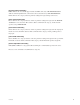
The items that are supported as the File Entry in the DSR-DR1000 are identified by the round marks (O) and by the triangle marks(T) in the following table. At the same time, the items that are shown with the crossing mark (X) are filled with 0x00 to create the FILE SYSTEM DATA.
(5) SYSTEM STATUS SENSE In the DSR-DR1000, the SYSTEM STATUS SENSE is the command that aims at inquiry of the SYSTEM STATUS (inquiring the VFL DOWNLOAD processing status check). Command format Item Size Value Description DC 1 0x04 Data Count CMD1 1 0x11 Command1 CMD2 1 0xD0 Command2 DATA1 2 0xXX TABLE NUMBER (Lower) 0xXX TABLE NUMBER (Upper) DATA2 2 0xXX REQUEST LENGTH (Lower) 0xXX REQUEST LENGTH (Upper) Requests that cannot be accepted due to their contents 1.
(7) FILE ENTRY DATA SENSE In the DSR-DR1000, the FILE ENTRY DATA SENSE is the command that aims at inquiry of the FILE ENTRY DATA (File Entry while recording/playback is in progress). Command format Item Size Value 1 0x03 Data Count CMD1 1 0x1A Command1 CMD2 1 0x82 Command2 DATA1 1 0xXX FILE HANDLE DATA2 1 0xXX TABLE NUMBER DATA3 1 0xXX REQUEST LENGTH DC Description Requests that cannot be accepted due to their contents 1. Requesting the FILE HANDLE using a value other than 0x00.
(9) CURRENT TIME SENSE In the DSR-DR1000, the CURRENT TIME SENSE is the command that aims at inquiry of the Current Time of the present status (when recording/playback is in progress).
(10) CURRENT TIME In the DSR-DR1000, the CURRENT TIME is the status that aims at returning the Current Time of the present status (while recording/playback is in progress).
(11) FILE OPEN STATUS SENSE In the DSR-DR1000, the FILE OPEN STATUS SENSE is the command that aims at inquiry of the FILE OPEN STATUS (status of OPEN PLAY). Command format Item Size Value Description DC 1 0x01 Data Count CMD1 1 0x10 Command1 CMD2 1 0x43 Command2 DATA1 1 0xXX PORT ID In the DSR-DR1000, PORT ID of the FILE OPEN STATUS SENSE is ignored. (12) FILE OPEN STATUS In the DSR-DR1000, the FILE OPEN STATUS is the status that aims at inquiry of the processing status of OPEN PLAY.
7-3. Items supported from DSR-DR1000/A disk command V2.00 1. Open Play Command supporting ENDLESS MODE In V2.00 or later, by setting ENDLESS MODE that exists in the Option of the Open Play Command, an opened file can be played back repeatedly.
*1: Select whether or not to specify CHANNEL. (Ignore Bit even when it is 1. However match Data’s offset.) 0 : Do not specify CHANNEL. 1 : Specify CHANNEL. *2: Select whether or not to specify the START position. 0 : Do not specify the START position. 1 : Specify the START position. *3: Select whether or not to specify DURATION. (Ignore Bit even when it is 1.) 0 : Do not specify DURATION. 1 : Specify DURATION. *4: Select whether or not to enable ENDLESS MODE. (Specifying this Bit activates Repeat Play.
2. Correction of the CLOSE Command In V2.00 or later, VFL can be downloaded during the CLOSE state. In V1.10 or later, at CLOSE after opening the VFL, a VFL that has the same name with the VFL that had been open could not be created. 3. “CR” and “LF” in the VFL DOWNLOAD SET Command In V1.10 or later, “CR” and “LF” were handled oppositely in the VFL Download Set Command. In V2.00 or later, in consideration of compatibility, operation can be performed with both “CR” “LF”, and “LF” “CR”. 4.
7-4. Special Commands for HVR Series In the HVR series, the extension commands are located in the DEVICE DEPENDENT area of the 9-pin command table. These commands interpret DATA-1 as CMD-3. 7-4-1. Command Table COMMAND RETURN HVR-1500 HVR-1500A 0X.FA.E5 : EXTEND VIDEO INPUT SELECT 10.01 : ACK X O 01.FB.E5 : EXTEND VIDEO INPUT SENSE 14.FB.E5 : EXTEND VIDEO INPUT STATUS X O 7-4-2. Detailed Description of Commands 0X.FA.
01.FB.E5 : EXTEND VIDEO INPUT SENSE This command is used to inquire video input selection status. Send back the “14.FB.E5 : EXTEND VIDEO INPUT STATUS” command to see the setting in DATA-2 to DATA-4. 14.FB.E5 : EXTEND VIDEO INPUT STATUS This command is used to send video input selection information in response to the “01.FB.E5 : EXTEND VIDEO INPUT SENSE” command.
8. Time Data Format The following shows the time data format used by commands such as “24.31 : CUE UP WITH DATA”. BIT7 BIT0 DF DATA-1 10F 1F DATA-2 10S 1S DATA-3 10M 1M DATA-4 10H 1H Although the shaded null bits have no meaning as time data, they are set in the following cases. 1. DATA 1 BIT-6 : DF FLAG (“1” DF, “0” NDF)...Only for NTSC model This bit is set in a response command from DEVICE of “61.0C : CURRENT TIME SENSE” according to the DF or NDF mode of DEVICE.
10. Appendix-2 (1) 44.04 [TIME CODE PRESET], 4X.05 [USER’S BIT PRESET] preset “10 : 10 : 10 : 00” Ext.
11. Appendix-3 (1) 40.C1 [TIMELINE RUN] When the DEVICE is requested to execute operation exactly when the above-described command is given, the DEVICE should be locked to the external reference video signal and the target command transmitted within 2 ms of the switching point of frames of the external sync video signal, or within 2 ms of the end of the first field. TIMELINE RUN REF. 2 ms 2 ms Field-1 TIMELINE Field-2 Field-1 N Field-2 N+1 (2) 44.
The material contained in this manual consists of information that is the property of Sony Corporation. Sony Corporation expressly prohibits the duplication of any portion of this manual or the use thereof for any purpose other than the operation or maintenance of the equipment described in this manual without the express written permission of Sony Corporation. Le matériel contenu dans ce manuel consiste en informations qui sont la propriété de Sony Corporation.
DSR-60 DSR-60P DSR-70 DSR-70P DSR-70A DSR-70AP DSR-80 DSR-80P DSR-85 DSR-85P DSR-1500 DSR-1500A DSR-1500P DSR-1500AP DSR-1600 DSR-1600A DSR-1600P DSR-1600AP DSR-1800 DSR-1800A DSR-1800P DSR-1800AP DSR-2000 DSR-2000A DSR-2000P DSR-2000AP DSR-DR1000 DSR-DR1000A DSR-DR1000P DSR-DR1000AP HVR-1500 HVR-1500A (CE, UC, CN) E 9-955-140-09 Sony Corporation Printed in Japan 2008.