2-347-750-11 (1) SRP-X700P Manager User Control Panel Operating Instructions (Control Software Manual Ver. 1.1) Before using the software, please read this manual and the Operating Instructions of the Digital Powered Mixer (main unit) thoroughly and retain it for future reference.
Table of Contents Features ........................................................................................................................... 3 Precautions ...................................................................................................................... 3 About This Manual ......................................................................................................... 3 Installation .......................................................................................
Features The CD-ROM supplied with the SRP-X700P contains two applications and the driver software. By installing the software in a personal computer running Windows, you can set the parameters of the SRP-X700P and can perform from the PC the basic operations of the SRP-X700P. Similarly, you can also operate a Sony DVD, VCR or CD/MD that is connected to the SRP-X700P. SRP-X700P Manager The SRP-X700P Manager enables you to set all the functions of the SRP-X700P.
Installation The dedicated USB driver software is necessary to connect the SRP-X700P Manager and User Control Panel to the SRP-X700P. 0 Select [Search for the best driver for your device. (Recommended).] and click [Next >]. (Fig. 3) Installing the Dedicated USB Driver Software Select • The dedicated USB driver software is contained in the CD-ROM supplied with the SRP-X700P. • Install the dedicated USB driver software by following the instructions shown on the screen.
Installing the SRP-X700P Manager Installing the User Control Panel 1 Insert the supplied CD-ROM into the CD-ROM drive of the personal computer. Open the SRP-X700P Manager folder. Double-click the Setup icon. 2 The SRP-X700P Manager installation screen appears. 3 When the screen [Welcome to the SRP-X700P Manager installation program] appears, click OK. 4 When the screen [Begin the installation by clicking the button below] appears, click the Setup icon on the top left of the screen. (Fig.
Section 1 SRP-X700P Manager The SRP-X700P Manager enables you to set all parameters of the SRP-X700P. Starting the SRP-X700P Manager If the SRP-X700P Manager is started after connecting the SRP-X700P to the personal computer with a USB cable, the present setup of the SRP-X700P is read. If the SRP-X700P Manager is started before connecting the SRP-X700P to the personal computer, the default setup of the SRP-X700P when shipped from the factory is read.
Edit menu (Displayed only on the INPUT and OUTPUT screens) 1 2 Bottom menu bar You can select the setup screen for each parameter. For the INPUT and OUTPUT buttons, submenus are displayed. Copy: Copies the parameters. 2 3 You can copy the parameters of the desired channel to the specified channel. Use this function when you want to use multiple channels with the same setup. However, you cannot copy the parameters of index, TRIM (INPUT), feedback reducer (INPUT) and REF LEVEL (OUTPUT).
Names and Functions of Controls on Screen 1.1 BLOCK Screen The BLOCK screen displays the setup status and the signal level according to the internal blocks in the SRP-X700P. If you click a button, the screen jumps to the related setup screen. You can select ON/OFF and set parameters on each screen. 3 4 56 7 8 9 qa qd qfqg qh qj qk 2 w; 1 ws wa 0 1 INPUT index You can enter an index of each input channel.
1.2 INPUT Screen You can set parameters of the input block of the SRP-X700P from the INPUT screen. 1.2.1 INPUT OVERVIEW Screen This screen corresponds to the input module of the audio mixer. This screen enables you to set the following. 4 5 qh 1 3 2 6 8 9 qk 7 q; qa qs qf qd qj qg 1 INPUT index Displays the index that is input on the BLOCK screen. 2 INPUT level meter Displays the input signal level after the TRIM adjustment is complete with the VU response.
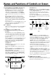
Names and Functions of Controls on Screen qd GAIN LIMIT and qf OVER GAIN indicators The sending level from input section is the sum of the qj INPUT fader and the input fader of the SRP-X700P. If the SRP-X700P master volume is manipulated and the sound volume is remotely controlled via the REMOTE terminal using the GROUP FADER screen and REMOTE screen respectively, these setup values are also added to the sum.
1.2.2 INPUT EQ Screen You can set the low-cut filter, feedback reducer and parametric equalizer of the SRP-X700P input block from the INPUT EQ screen. 1 2 3 8 9 0 4 5 6 7 1 Channel select button Selects the INPUT channel that you want to set. The selected button lights in yellow. 2 INPUT index Displays the index that is input on the BLOCK screen. 3 Frequency response graph Displays the overall frequency response characteristics of the low-cut filter, parametric equalizer and feedback reducer.
Names and Functions of Controls on Screen Parametric Equalizer Block The MIC1/WL1, MIC2/WL2, MIC3, MIC4, MIC5/LINE1 and MIC6/LINE2 channels have a 3-band parametric equalizer, and the LINE3 and LINE4 channels have a 2-band parametric equalizer. Clicking the v or V button changes the following parameters of each band. You can also enter numerical values directly. You can change the center frequency and the GAIN by dragging the marker portion with the mouse. Q can be entered on the Q setup box.
1.3 ROUTING Screen On this screen, you can set to which output channel the input signal is to be output. 4 1 2 3 1 INPUT index Displays the INPUT channel index that is entered on the BLOCK screen. 2 OUTPUT index Displays the OUTPUT channel index that is entered on the BLOCK screen. 3 ASSIGN button You can select the signal input and output path. Right-clicking the button displays the menu. You can select the desired sending level from –20 dB, –15 dB, –12 dB, –9 dB, –6 dB, –3 dB or 0 dB.
Names and Functions of Controls on Screen 1.4 OUTPUT Screen You can set the parameters of the output block of the SRP-X700P from the OUTPUT screen. 1.4.1 OUTPUT OVERVIEW Screen This screen corresponds to the output module of the audio mixer. This screen enables you to set the following. The OUTPUT 1 through OUTPUT 8 correspond to the LINE OUTPUT 1 through LINE OUTPUT 8 of the main unit.
qf FADER select and qg OUTPUT fader The qg OUTPUT fader has the two modes of ACTIVE and INACTIVE. To switch the fader mode, click the qf FADER select. The selected mode lights in yellow. The yellow marker displayed on the side of the fader indicates the fader position that is the addition of the qg OUTPUT fader setup.
Names and Functions of Controls on Screen 1.4.2 OUTPUT EQ Screen You can set the equalizer of the SRP-X700P output block from the OUTPUT EQ screen. 1 2 3 4 5 6 7 5 6 7 5 6 7 8 1 Channel select button Selects the OUTPUT channel that you want to set. The selected button lights in yellow. 2 OUTPUT index Displays the index that is entered on the BLOCK screen. 3 Frequency response graph Displays the overall frequency response characteristics of the high-cut filter and parametric equalizer.
1.5 REMOTE Screen You can establish various setups of the remote terminal from the REMOTE screen. 1 2 3 4 6 qa qf q; 5 qs qd 8 9 7 PARALLEL I/O Block MACHINE CONTROL Block 1 PARALLEL INPUT indicator You can establish various setups to control Sony products through the Control-S output terminal. For details of the connection and other procedures, refer to “How to Control AV Equipment from the SRP-X700P” of the SRP-X700P Operating Instruction. Displays the status of the parallel input terminal.
Names and Functions of Controls on Screen qd SIGNAL DEFINE setup box PROJECTOR CONTROL Block You can establish various setups to control a projector, refer to “How to Control the Display from the SRP-X700P” of the SRPX700P Operating Instruction. q; I/F TYPE The connection method that corresponds to the projector selected by qa PROJECTOR PROTOCOL setup box, is displayed. qa PROJECTOR PROTOCOL setup box Selects a projector that is to be connected to the PROJECTOR CONTROL terminal.
Parameters in the PARALLEL INPUT FUNCTION setup box Function NONE: Does not set any function. AV SEL: Selects the LINE4 input. LVL+: Increases the sound volume with an external switch. LVL–: Decreases the sound volume with an external switch. LVL: Adjusts the sound volume with an external sound volume controller. Muting: Performs muting. RECALL: Recalls the desired scene No. LINE3 Control: Controls the device connected to LINE3. LINE4 Control: Controls the device connected to LINE4.
Names and Functions of Controls on Screen USER DEFINE Screen Use this screen to set the communication protocol when USER DEFINE is selected in the PROJECTOR PROTOCOL setup box. When USER DEFINE is selected, the projector is connected to the PROJECTOR CONTROL RS-232C terminal. Once the communication protocol between the SRP-X700P and projector has been set, the projectors not supported by default can be connected. Note The above-described setup does not guarantee operation of all projectors.
Port setup Sets the communication conditions between the SRP-X700P and projectors. 5 4 4 BITS PER SECOND setup box Sets the baud rate. Select the desired speed to 9600, 19200, or 38400 bps depending on the baud rate of the projector. 5 PARITY BIT setup box Sets the parity bit. Select NONE, ODD, or EVEN depending on the communication data specifications of the projector. PROJECTOR POWER ON setup Sets the command to turn on the projector power and sets the wait time after the command has been sent.
Names and Functions of Controls on Screen INPUT SELECT command setup Sets the command to select the input terminal of the projector in accordance with the SRP-X700P LINE4 SELECT selection. It also sets the wait time after the command has been sent. The SRP-X700P has built-in independent switchers for the respective video signal systems. When the video signal system of the channel that is selected by LINE4 SELECT is the VIDEO signal, the output video signal is sent to the VIDEO output terminal.
Connectable projectors Projectors meeting the following specifications can be connected. • Equipped with RS-232C remote terminal • The RS-232C remote terminal must support the following specifications. Electrical characteristics : Conforming to RS-232C Baud rate : 9600, 19200 or 38400 bps Parity bit : None, odd or even Data length : 8 bits Stop bit : 1 bit Flow control : None • The RS-232C remote terminal can be used to turn on the power, turn off the power, and select the input terminal.
Names and Functions of Controls on Screen Connection to projector For details of the method of connecting to a projector, see “System example when operating the SRP-X700P with the default setting when shipped from the factory” of the SRP-X700P Operating Instructions. When the RGB signal distributor to be connected to the projector, connect them as shown below.
5. Input select operation check using the TEST button 1 Do not input any signal to LINE4 INPUT of the SRPX700P. Select VIDEO using the signal format select button and press the TEST button in the INPUT SELECT command setup. 2 Confirm that VIDEO is selected as the input signal to the projector. 3 Execute the same confirmation as in steps 1 and 2 for all signal systems.
Names and Functions of Controls on Screen 1.6 GROUP FADER Screen You can group several faders in order to move multiple internal faders from the Remote terminal or from the Master volume control of the SRP-X700P. 1 2 4 3 5 1 FADER GROUP index Enters the index of the FADER GROUP. You can enter up to 8 alphanumeric characters. 2 INPUT index Displays the INPUT index that is entered on the BLOCK screen. 3 OUTPUT index Displays the OUTPUT index that is entered on the BLOCK screen.
1.7 SCENE Screen You can set scenes from this screen. You can store the setups on each screen of INPUT, ROUTING, OUTPUT and GROUP FADER into the internal memory of the SRP-X700P or call them from the scene memory. 1 2 3 5 7 4 6 9 8 SCENE block You can recall, store or clear the scenes. To recall the scene that is set • Select the scene No. that you want to recall, using the 1 SCENE No. button. • Click the 2 RECALL button. To memorize the parameter that is set • Select the scene No.
Section 2 User Control Panel The User Control Panel software enables you to operate the SRP-X700P more simply from a personal computer that you may use for presentations and other purposes. Note Start up the User Control Panel after connecting the SRP-X700P to the personal computer. To connect the SRP-X700P to the personal computer, use a USB cable (TYPE-B).
Troubleshooting Before contacting a Sony Sales office or Dealer, check the following again. If the trouble persists, contact your local Sony Sales office or Dealer. Symptom Cause/Remedy Cannot operate the system from User • USB cable is not connected. Control Panel. Cannot operate the system using → Check the connection of the USB cable. • The dedicated USB driver software is not installed. SRP-X700P Manager. Index is not displayed when using User Control Panel. Cannot operate FADER by remote control.