CAPSULE UNIT CU-F780 CU-G780 CU-E700 CU-E672 CU-F117 SERVICE MANUAL 1st Edition
! WARNING This manual is intended for qualified service personnel only. To reduce the risk of electric shock, fire or injury, do not perform any servicing other than that contained in the operating instructions unless you are qualified to do so. Refer all servicing to qualified service personnel. ! WARNUNG Die Anleitung ist nur für qualifiziertes Fachpersonal bestimmt. Alle Wartungsarbeiten dürfen nur von qualifiziertem Fachpersonal ausgeführt werden.
Table of Contents 1. Operating Instructions ..................................................................... 1-1 2. CU-F780/CU-G780 2-1. 2-2. 2-3. 2-4. Service Overview ........................................................................................ 2-1 2-1-1. Notes on Attaching the CN-2089 Board .................................... 2-1 Board Layout ............................................................................................... 2-1 Schematic Diagrams............................
-4-3. 4-4-4. Electrical Parts List .................................................................... 4-6 Supplied Accessories ................................................................. 4-6 5. CU-F117 5-1. 5-2. 5-3. 5-4. 2 Service Overview ........................................................................................ 5-1 5-1-1. Notes on Attaching the CN-2089 Board .................................... 5-1 Board Layout ...................................................................
Section 1 Operating Instructions 3-205-156-02 (1) Reprinted from the operating instructions English B CU-G780 The CU-F780/CU-G780/CU-E700/CU-E672/CU-F117 are the Microphone Capsule Units designed for the WRT-847A/WRT847B Sony UHF synthesized transmitter unit to be used in a Sony UHF synthesized wireless microphone system.
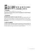
Frequency response and directivity 90˚ 90˚ CU-F780 CU-E672 0˚ 180˚ 0˚ 20 20 10 10 0 Response (dB) Response (dB) 0 -10 -20 -30 180˚ 20 50 100 200 500 1k 2k 5k 10k 20k -10 -20 -30 Hz 20 50 100 Frequency (Hz) 200 500 1k 2k 5k 20k Hz 0˚ 90˚ 180˚ Uni-directional Uni-directional 0˚ 30˚ 15˚ 30˚ 0dB 30˚ -5 60˚ 0˚ 15˚ 30˚ 0dB -5 45˚ -10 60˚ 45˚ -10 60˚ -15 60˚ -15 75˚ 75˚ -20 -20 90˚ 90˚ 90˚ 90˚ 105˚ 120˚ 100 Hz 1 kHz 6 kHz 120˚ 105˚ 120˚ 150˚ 250
2. CU-F780/CU-G780 2-1. Service Overview 2-1-1. Notes on Attaching the CN-2089 Board B 2x4 (three) Grip 1 CN-2089 board SONY logo Grip 1 Place the PC board in the unit with the SONY logo facing you, and align the board so that the nub on the board fits into the small indentation on the unit. 2-2.
CN-2089 2-3. Schematic Diagrams 1 ECM-WHT R101 27k VCC DM-UNIT R102 39k ECM-VCC(5.
2-4. Spare Parts 2-4-1. Notes on Repair Parts 1. Safety Related Components Warning w Components marked ! are critical to safe operation. Therefore, specified parts should be used in the case of replacement. 2. Standardization of Parts Some repair parts supplied by Sony differ from those used for the unit. These are because of parts commonality and improvement. Parts list has the present standardized repair parts. 3.
2-4-2. Exploded Views and Parts List 2 B 2x4 4 5 1 6 3 2-4-3. Electrical Parts List ------------CN-2089 BOARD ------------Ref. No. or Q’ty Part No. Description 1 2 3 A-8265-752-B A-8327-861-A A-8327-860-A X-3608-171-1 X-3678-174-2 s s s s s DM UNIT ASSY (V4.1) (For CU-F780) CAPSULE (V4.01) ASSY, DM PS (For CU-G780) MOUNTED CIRCUIT BOARD, CN-2089 ASSY, CAGE (RS) (For CU-G780) CAGE ASSY (For CU-F780) 4 5 6 1-961-058-11 3-631-750-01 3-682-258-01 o o s HARNESS, SUB (B) RING SCREEN 2-4-4.
3. CU-E700 3-1. Service Overview 3-1-1. Notes on Attaching the CN-2089 Board B 2x4 (three) CN-2089 board Grip 1 SONY logo Grip 1 Place the PC board in the unit with the SONY logo facing you, and align the board so that the nub on the board fits into the small indentation on the unit. 3-2. Board Layout MA-56 Board (SOLDER SIDE) R102 16 K BLK RED WHT C102 4.7 µ D1 R2 39 k MA-56 Board (COMPONENT SIDE) D2 UMZ8.
CN-2089 ,MA-56 3-3. Schematic Diagrams 1 D101 UMZ8.2T-T106 ECM-WHT WHT Q101 2SK67A-J5 C103 22uF 10V VCC 1 2 BLK D102 UMZ8.2T-T106 GND 1 2 3 R102 39k ECM-VCC(5.8V) S 2 1 MIC1 NM 2 R1 2500M C101 47pF 50V RED C102 4.
3-4. Spare Parts 3-4-1. Notes on Repair Parts 1. Safety Related Components Warning w Components marked ! are critical to safe operation. Therefore, specified parts should be used in the case of replacement. 2. Standardization of Parts Some repair parts supplied by Sony differ from those used for the unit. These are because of parts commonality and improvement. Parts list has the present standardized repair parts. 3.
3-4-2. Exploded Views and Parts List B 2x4 1 10 4 B 2x4 11 2 5 9 6 P 2x6 8 No. Part No.
4. CU-E672 4-1. Service Overview 4-1-1. Disassembly Grip SG, Joint CN-2089 Board Grip SG Joint CN-2089 board B 2x4 (three) Unsolder 2 1 M 2.6x4 Cabinet Precision K 2x5 to page 4-2 Cabinet Precision K 2x3.5 Unfasten the two screws (+K 2x3.5 and +K 2x5). (Torque: 2.5 kgf·cm) Top screen Top cap Precision K 1.7x3 (three) Caution: When reinstalling, first tighten the +K 2x3.5 screw that secures the chassis assy and the capsule base assy. Unfasten the three +K 1.7x3 screws. (Torque: 0.
Capsule Black Assy Capsule Comple Pwb, Capsule Base Assy Capsule cushion MA-109 board Capsule complete pwb Red lead Capsule base assy White lead Caution: . When reinstalling the white and red leads, slack off the leads as shown above and be sure not to come in contact with each other and the inside of the capsule cushion. . After soldering the leads, apply bond (SC608-LUZ) to the parts circled with a dotted line in the illustration to keep the leads from breaking. Precision +K 1.
4-1-2. Notes on Attaching the CN-2089 Board B 2x4 (three) Joint CN-2089 board SONY logo Joint Place the PC board in the unit with the SONY logo facing you, and align the board so that the nub on the board fits into the small indentation on the unit. 4-2. Board Layout WHT R1 2000M RED MA-109 C2 0.33 µ 35 V S CAPSULE RED R2 24 K Q1 [|DIODE|] BLU BLK R3 24 K C3 100 µ 10 V WHT T1 YEL C1 15P [|TRANSISTOR|] D1 -TOP VIEW- UMZ8.2T-T106 R2 39 k 2SK67A-J5 D2 UMZ8.
CN-2089, MA-109 4-3. Schematic Diagrams 1 D101 UMZ8.2T-T106 ECM-WHT WHT VCC 1 2 C103 100uF 10V Q101 2SK67A-J5 BLK D102 UMZ8.2T-T106 GND 1 2 3 R102 39k ECM-VCC S 2 1 MIC1 NM R101 2000M C101 15pF 2 BLUE C102 0.
4-4. Spare Parts 4-4-1. Notes on Repair Parts 1. Safety Related Components Warning w Components marked ! are critical to safe operation. Therefore, specified parts should be used in the case of replacement. 2. Standardization of Parts Some repair parts supplied by Sony differ from those used for the unit. These are because of parts commonality and improvement. Parts list has the present standardized repair parts. 3.
4-4-2. Exploded Views and Parts List No. Part No. SP Description 1 2 3 4 5 A-4510-072-A A-8327-846-A A-8327-847-A 2-044-301-01 2-523-713-00 s s s s s COMPLETE PWB, CAPSULE MOUNTED CIRCUIT BOARD, MA-109 MOUNTED CIRCUIT BOARD, CN-2089 (ECM) LUG TERMINAL 6 7 8 9 10 2-539-410-01 2-539-418-01 2-539-425-01 2-539-427-01 3-631-721-01 s o s o o SCREEN, TOP SCREEN, BASE CAP, TOP CASE, SHIELD GRIP SG K 2x5 15 B A K 2x3.5 6 K 1.7x3 8 B 2x4 13 3 12 14 M 2.
5. CU-F117 5-1. Service Overview 5-1-1. Notes on Attaching the CN-2089 Board B 2x4 (three) Joint CN-2089 board SONY logo Joint Place the PC board in the unit with the SONY logo facing you, and align the board so that the nub on the board fits into the small indentation on the unit. 5-2.
CN-2089 5-3. Schematic Diagrams 1 ECM-WHT R102 39k VCC OMNI-UNIT ECM-VCC(5.
5-4. Spare Parts 5-4-1. Notes on Repair Parts 1. Safety Related Components Warning w Components marked ! are critical to safe operation. Therefore, specified parts should be used in the case of replacement. 2. Standardization of Parts Some repair parts supplied by Sony differ from those used for the unit. These are because of parts commonality and improvement. Parts list has the present standardized repair parts. 3.
5-4-2. Exploded Views and Parts List 6 8 3 9 B 2x4 1 4 7 5 8 2 5-4-3. Electrical Parts List ------------CN-2089 BOARD ------------Ref. No. or Q’ty Part No. SP Description A-8327-852-A s MOUNTED CIRCUIT BOARD, CN-2089 1-961-058-11 o HARNESS, SUB (B) R102 1-216-689-11 s RESISTOR,CHIP 39K 1/10W(2012) 1pc 5-4 No. Part No.
CU-F780 (SY) CU-G780 (SY) CU-E700 (SY) Printed in Japan CU-E672 (SY) CU-F117 (SY) E 9-976-895-01 (1) 2001.