2-694-840-12(2) Multi Channel AV Receiver Operating Instructions STR-DA1200ES Sony Corporation Printed in Malaysia ©2006 Sony Corporation
WARNING To reduce the risk of fire or electric shock, do not expose this apparatus to rain or moisture. To prevent fire, do not cover the ventilation of the apparatus with news papers, table-cloths, curtains, etc. And don’t place lighted candles on the apparatus. To prevent fire or shock hazard, do not place objects filled with liquids, such as vases, on the apparatus. Do not install the appliance in a confined space, such as a bookcase or built-in cabinet.
About This Manual • The instructions in this manual are for model STRDA1200ES. Check your model number by looking at the lower right corner of the front panel. • The instructions in this manual describe the controls on the supplied remote. You can also use the controls on the receiver if they have the same or similar names as those on the remote. This receiver incorporates Dolby* Digital and Pro Logic Surround and the DTS** Digital Surround System. * Manufactured under license from Dolby Laboratories.
Table of Contents Getting Started Description and location of parts ..................6 1: Installing speakers ..................................16 2: Connecting speakers ...............................17 3a: Connecting the audio components ........19 3b: Connecting the video components .......24 4: Connecting the antennas (aerials) ...........35 5: Preparing the receiver and the remote ....36 6: Setting the speakers ................................
Watching component images from other inputs (COMPONENT VIDEO ASSIGN) ...... 88 Changing the display .................................. 89 Using the Sleep Timer ................................ 90 Recording using the receiver ...................... 90 Using a bi-amplifier connection ................. 91 Using the Remote Operating each component using the remote .................................... 93 Programming the remote ............................ 94 Clearing all the contents of the remote’s memory ....
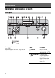
Getting Started Description and location of parts Front panel To remove the cover Press PUSH. When you remove the cover, keep it out of reach from children. Name Function A POWER Press to turn the receiver on or off (page 36, 48, 49, 50, 51, 76). B AUTO CAL MIC Connects to the jack supplied optimizer microphone for the Digital Cinema Auto Calibration function (page 40).
Function Name Function Adjusts FRONT BASS and FRONT TREBLE. Press TONE MODE repeatedly to select BASS or TREBLE, then turn TONE to adjust the level (page 57). L INPUT MODE Press to select the input mode when the same components are connected to both digital and analog jacks (page 85). M MULTI CH IN Press to select the audio input signal from the component connected to the MULTI CHANNEL INPUT jack (page 47). N A.DIRECT Press to listen to high quality analog sound (page 74).
About the indicators on the display Name Function Name Function A SW Lights up when sub woofer selection is set to “YES” and the audio signal is output from the SUB WOOFER jack (page 63). While this indicator lights up, the receiver creates a sub woofer signal based on the L.F.E. signal in the disc being played back or the low frequency components of the front channels. B Playback channel indicators The letters (L, C, R, etc.) indicate the channels being played back.
Name Function D INPUT Lights up constantly. One of the input indicators also lights up according to the current input. E AUTO Lights up when INPUT MODE is set to “AUTO” (page 85). F HDMI Lights up when the receiver recognizes a component connected via an HDMI IN jack (page 25). G DTS (-ES) Lights up when the receiver is decoding DTS signals. “DTS-ES” also lights up when the receiver is decoding DTS-ES signals.
Name Function Name R L.F.E. Lights up when the disc being played back contains an L.F.E. (Low Frequency Effect) channel and the L.F.E. channel signal is actually being reproduced, the bars underneath the letters light up to indicate the level. Since the L.F.E. signal is not recorded in all parts of the input signal the bar indication will fluctuate (and may turn off) during playback. W SP-A/SP-B/ Lights up according to the SP-OFF speaker system used (page 38).
Rear panel Getting Started A DIGITAL INPUT/OUTPUT section OPTICAL IN/ Connects to a DVD OUT jacks player, Super Audio CD player, etc. The COAXIAL jack COAXIAL IN provides a better quality sound (page jacks 19, 20, 29). HDMI IN/ MONITOR OUT jacks Connects to a DVD player, or a satellite tuner. An image and the sound are output to TV or a projector (page 25). B ANTENNA section FM ANTENNA Connects to the FM jack wire antenna (aerial) supplied with this receiver (page 35).
E VIDEO/AUDIO INPUT/OUTPUT section L AUDIO IN/ OUT jacks R Connects to a VCR or a DVD player etc. (page 29, 30, 31, 32). VIDEO IN/ OUT jacks* S VIDEO IN/ OUT jacks* F SPEAKERS section Connects to speakers (page 17). * You can watch the selected input image when you connect the MONITOR OUT jack to a TV (page 27). You can also display certain menu settings and the sound field on the monitor when you press ON SCREEN on the remote (page 83).
Remote commander Function A AV ?/1 Press to turn on or off the audio/ (on/standby) video components that the remote is assigned to operate (page 94). If you press the ?/1 (B) at the same time, it will turn off the receiver and other Sony components (SYSTEM STANDBY). Note The function of the AV ?/1 switch changes automatically each time you press the input button (C). RM-AAP015 B ?/1 Press to turn the receiver on or (on/standby) off.
Name Function Name Function H Numeric buttons Press to – preset/tune to preset stations. – select track numbers of the CD player, DVD player or MD deck. Press 0/10 to select track number 10. – select channel numbers of the VCR or satellite tuner. – After pressing TV (wj), press the numeric buttons to select the TV channels. Q F1/F2 Press TV (wj) and then press F1 or F2 to select a component to operate.
Function X CLEAR Press to – clear a mistake when you press the incorrect numeric button. – return to continuous playback, etc. of the satellite tuner or DVD player. >10 Press to select – track numbers over 10 of the VCR, satellite tuner, CD player or MD deck. – channel numbers of the Digital CATV terminal. D.TUNING Press to enter direct tuning mode (page 78). Y A.DIRECT Press to switch the audio of the selected input to analog signal without any adjustment (page 74).
1: Installing speakers This receiver allows you to use a 7.1 channel system (7 speakers and one sub woofer). Enjoying a 5.1/7.1 channel system To fully enjoy theater-like multi-channel surround sound requires five speakers (two front speakers, a center speaker, and two surround speakers) and a sub woofer (5.1 channel system). two surround back speakers (7.1 channel system). (see “Using the surround back decoding mode (SB DECODING)” on page 60). Example of a 7.
2: Connecting speakers G F A E D Getting Started H FRONT SPEAKERS B terminals a) B C B A A Monaural audio cord (not supplied) B Speaker cords (not supplied) AFront speaker A (L) BFront speaker A (R) CCenter speaker DSurround speaker (L) ESurround speaker (R) FSurround back speaker (L)b) GSurround back speaker (R)b) HSub wooferc) a) If you have an additional front speaker system, connect them to the FRONT SPEAKERS B terminals.
c) When you connect a sub woofer with an auto standby function, turn off the function when watching movies. If the auto standby function is set to on, it turns to standby mode automatically based on the level of the input signal to a sub woofer, then sound may not be output. Note When you connect all the speakers with a nominal impedance of 8 ohms or higher, set “SP. IMPEDANCE” in the System Settings menu to “8 ohm.” In other connections, set it to “4 ohm.
3a: Connecting the audio components Audio input/output jacks to be connected This section describes how to hook up your components to this receiver. Before you begin, refer to “Component to be connected” below for the pages which describe how to connect each component. After hooking up all your components, proceed to “4: Connecting the antennas (aerials)” (page 35). Component to be connected Super Audio CD player/ CD player MD/TAPE Analog disc turntable The sound quality depends on the jack used.
Connecting components with digital audio input/output jacks The following illustration shows how to connect a Super Audio CD player, CD player and an MD/TAPE deck.
Notes on playing a Super Audio CD on a Super Audio CD player Getting Started • No sound is output when playing a Super Audio CD on a Super Audio CD player connected to only the COAXIAL SA-CD/ CD IN jacks on this receiver. When you play a Super Audio CD, connect the player to the MULTI CHANNEL INPUT or SA-CD/CD IN jacks. Refer to the operating instructions supplied with the Super Audio CD player. • You cannot make digital recordings of a Super Audio CD. Use the analog jack for recording in this case.
Connecting components with multi-channel output jacks If your DVD or Super Audio CD player is equipped with multi-channel output jacks, you can connect it to the MULTI CHANNEL INPUT jacks of this receiver to enjoy multichannel sound. Alternatively, the multichannel input jacks can be used to connect an external multi-channel decoder. DVD player, Super Audio CD player, etc.
Getting Started Connecting components with analog audio jacks The following illustration shows how to connect a component with analog jacks, such as tape deck, turntable, etc. Super Audio CD player, CD player MD deck, TAPE deck A A A Turntable A Audio cord (not supplied) Note If your turntable has a ground (earth) wire, connect it to the (U) SIGNAL GND terminal.
3b: Connecting the video components How to hook up your components Video input/output jacks to be connected This section describes how to hook up your components to this receiver. Before you begin, refer to “Component to be connected” below for the pages which describe how to connect each component. After hooking up all your components, proceed to “4: Connecting the antennas (aerials)” (page 35).
Getting Started Connecting components with HDMI jacks HDMI is the abbreviated name for HighDefinition Multimedia Interface. It is an interface which transmits video and audio signals in digital format. DVD player Audio signals Satellite tuner/TV monitor, projector, etc. Audio/video signals B Audio signals A Audio/video signals C A A A HDMI cable (not supplied) We recommend that you use a Sony HDMI cable.
Notes on HDMI connections • Audio signals input to the HDMI IN jacks are output from the HDMI OUT jack. The input audio signals are not output from the speaker output jacks, PRE OUT jacks and any other audio output jacks. • You must connect audio or digital cords to output sound from the receiver (page 29, 31). • Video signals input to the HDMI IN jack can only be output from the HDMI OUT jack. The input video signals cannot be output from the VIDEO OUT jacks, S VIDEO OUT jacks, or MONITOR OUT jacks.
Connecting a TV monitor Getting Started The image from a visual component connected to this receiver and the menu of this receiver can be displayed on a TV screen. It is not necessary to connect all the cables. Connect audio and video cords according to the jacks of your components.
Notes • Connect image display components such as a TV monitor or a projector to the MONITOR OUT jack on the receiver. You may not be able to record, even if you connect recording components. • Turn on the receiver when the video and audio of a playback component are being output to a TV via the receiver. If the power supply of the receiver is not turned on, neither video nor audio is transmitted.
The following illustration shows how to connect a DVD player/DVD recorder. It is not necessary to connect all the cables. Connect audio and video cords according to the jacks of your components. Note To output multi-channel digital audio, set the digital audio output setting on the DVD player. Refer to the operating instructions supplied with the DVD player.
Connecting a DVD recorder DVD recorder Audio signals A Video signals B A Optical digital cord (not supplied) B Audio cord (not supplied) C Video cord (not supplied) D S video cord (not supplied) 30GB C D
Connecting a satellite tuner Getting Started The following illustration shows how to connect a satellite tuner. It is not necessary to connect all the cables. Connect audio and video cords according to the jacks of your components.
Connecting components with analog video and audio jack The following illustration shows how to connect a component which has analog jacks such as a VCR, etc. It is not necessary to connect all the cables. Connect audio and video cords according to the jacks of your components.
This receiver is equipped with a function for converting video signals. You can output the video signal after connecting this receiver via the MONITOR OUT jack as shown in the illustration. • Composite video signals can be output as S video signals and component video signals. • S video signals can be output as component video signals.
Notes on converting video signals Closed Caption display • You cannot down-convert input signals using the receiver. Component video signals cannot be converted to S video signals and composite video signals. S video signals cannot be converted to composite video signals. HDMI video signals cannot be converted to component video signals, S video signals, and video signals. • When video or S video signals from a VCR, etc.
4: Connecting the antennas (aerials) Getting Started Connect the supplied AM loop antenna (aerial) and FM wire antenna (aerial). FM wire antenna (aerial) (supplied) AM loop antenna (aerial) (supplied) * The shape of the connector varies depending on the area. Notes • To prevent noise pickup, keep the AM loop antenna (aerial) away from the receiver and other components. • Be sure to fully extend the FM wire antenna (aerial).
5: Preparing the receiver and the remote Connecting the AC power cord (mains lead) Connect the supplied AC power cord (mains lead) to the AC IN terminal on the receiver, then connect the AC power cord (mains lead) to a wall outlet. AC OUTLET* AC IN terminal • Make sure that the total power consumption of the component(s) connected to the receiver’s AC OUTLET(s) does not exceed the wattage stated on the rear panel.
Insert two R6 (size-AA) batteries in the RMAAP015 remote commander. Observe the correct polarity when installing batteries. RM-AAP015 Notes • Do not leave the remote in an extremely hot or humid place. • Do not use a new battery with old ones. • Do not mix manganese batteries and other kinds of batteries. • Do not expose the remote sensor to direct sunlight or lighting apparatuses. Doing so may cause a malfunction.
To switch the command mode of the RM-AAP015 remote 1 6: Setting the speakers Setting the speaker impedance Set the appropriate speaker impedance for the speakers you are using. 1 2 2 3 1 Press RM SET UP. The RM SET UP button flashes. 2 Press 1 or 2 while the RM SET UP button is flashing. 4-6 When you press 1, the command mode is set to AV SYSTEM 1. When you press 2, the command mode is set to AV SYSTEM 2. 3 Press ENTER when the RM SET UP button lights up.
6 Press MENU to exit the menu. Note You cannot switch the front speakers by pressing SPEAKER (OFF/A/B/A+B) when the headphones are connected to the receiver. Set to To select A The speakers connected to the FRONT SPEAKERS A terminals. B The speakers connected to the FRONT SPEAKERS B terminals. A+B The speakers connected to both the FRONT SPEAKERS A and B terminals (parallel connection). OFF No audio signals are output from any speaker terminals, or the PRE OUT terminal.
7: Calibrating the appropriate settings automatically (AUTO – MULTI IN is selected. – The ANALOG DIRECT function is being used. – Headphones are connected. • Cancel MUTING if it is set to on. Optimizer microphone CALIBRATION) The DCAC (Digital Cinema Auto Calibration) function allows you to perform automatic calibration, such as checking the connection between each speaker and the receiver, adjusting the speaker level, and measuring the distance of each speaker from your listening position automatically.
Getting Started 1 3 Note Depending on the characteristics of the sub woofer you are using, the setup distance value may be further away from the actual position. Using the receiver as a preamplifier You can use the auto calibration function when you use the receiver as a pre-amplifier. In this case, the distance value shown on the display may differ from the actual distance value. However, there will be no problems even if you continue to use the receiver with that value.
6 7 8 Press V/v repeatedly to select “CAL TYPE,” then press to enter the parameter. Press V/v repeatedly to select the parameter, then press to enter the selection. Calibration type Explanation ENGINEER Sets the frequency characteristics to a set that matches that of the Sony listening room standard. FULL FLAT Makes the measurement of frequency from each speaker flat. FRONT REF Adjusts the characteristics of all the speakers to match the characteristics of the front speaker.
1 Confirm the measurement result. When the measurement ends, a beep sounds and the measurement result appears on the display. Measurement Display result 2 Explanation When the measurement process completes properly COMPLETE Proceed to step 2. When the measurement process fails ERROR CODE XX Item Explanation DIST.INFO Displays the measurement result for speaker distance. LEVEL INFO Displays the measurement result for speaker level.
Error code Cause and remedies Warning code Explanation CODE 33 (SR) • Either the left or right surround speakers is not connected. • Surround back speakers are connected even though surround speakers are not connected. Connect the surround speaker to the SURROUND terminals. WARNING 41 The sound input from the optimizer microphone is outside the acceptable range. It is louder than the loudest sound that can be measured.
Explanation IN-PHASE The speaker is in phase. OUT-OFPHASE The speaker is out of phase. The “+” and “–” terminals of the speaker may be connected the other way around. However, depending on the speakers, “OUT-OF-PHASE” appears on the display even though the speakers are connected properly. This is because of the speakers’ specifications. In this case, you can continue to use the receiver. ---------- No speakers are connected.
x A.CAL LOAD? (Loads a preset measurement) • PRESET-1 Loads the measurement value stored as “PRESET-1.” • PRESET-2 Loads the measurement value stored as “PRESET-2.” • PRESET-3 Loads the measurement value stored as “PRESET-3.” • OFF Select this when you do not want to load a preset value. x A.CAL SAVE? (Saves the measurement value) • PRESET-1 Saves the measurement results as “PRESET-1.” • PRESET-2 Saves the measurement results as “PRESET-2.” • PRESET-3 Saves the measurement results as “PRESET-3.” x A.
Playback Selecting a component 3 MUTING 1 Press one of the input button. You can also use INPUT SELECTOR on the receiver. The selected input appears on the display. To select a component connected to the MULTI CHANNEL INPUT jack, press MULTI CH IN button. Switch the input signals from the component connected to the HDMI IN jack of the receiver to HDMI signals using the TV, etc., connected to the HDMI MONITOR OUT jack of the receiver. Components that can be played back VIDEO 1, 2 VCR, etc.
Listening to a Super Audio CD/CD 2 3 5 3 5 • The operation is described for a Sony Super Audio CD player. • Refer to the operating instructions supplied with the Super Audio CD player or CD player. 1 Turn on the Super Audio CD player or CD player, then place the disc in the tray. 2 3 Turn on the receiver. You can also use INPUT SELECTOR on the receiver to select “SA-CD/CD.” z You can select the sound field to suit the music. Refer to page 71 for details.
Watching a DVD Playback 2 3 7 3 MULTI CHANNEL DECODING lamp 7 • Refer to the operating instructions supplied with the TV and DVD player. z 1 2 3 Turn on the TV and DVD player. Turn on the receiver. Press DVD. Select the sound format of the disc to be played, if necessary. You can also use INPUT SELECTOR on this receiver to select “DVD.” z An example of the display You can select the sound field to suit the movie or the music. Refer to page 71 for details.
Enjoying video games 2 3 7 3 7 • Refer to the operating instructions supplied with the TV and video game. VIDEO 3 IN/PORTABLE AV IN 1 2 3 Turn on the TV and video game. Turn on the receiver. Press VIDEO 3*. You can also use INPUT SELECTOR on this receiver to select “VIDEO 3*.” * When you connect a TV game to the VIDEO 3 IN/PORTABLE AV IN jack on the front panel. An example of the display 50GB 4 Switch the input of the TV so that an image of the video game is displayed. 5 6 Set up the video game.
Watching video Playback 2 3 6 3 6 • Refer to the operating instructions supplied with the TV and VCR. 1 2 3 Turn on the VCR. Turn on the receiver. Press VIDEO 1*. You can also use INPUT SELECTOR on this receiver to select “VIDEO 1*.” * When you connect VCR to the VIDEO 1 jack. An example of the display 4 Switch the input of the TV so that an image of the VCR is displayed. 5 6 7 Play back the tape on the VCR. Adjust to a suitable volume.
To return to the previous display Amplifier Operations Press RETURN/EXIT O. Navigating through menus To exit the menu Press MENU. By using the amplifier menus, you can make various adjustments to customize the receiver. 1 3-7 RETURN/ EXIT O 1 2 Press RECEIVER. Receiver operation is enabled. 2 Press MENU. The list of setting menus appears. 3 Press V/v repeatedly to select the menu you want. 4 5 Press to enter the menu. Press V/v repeatedly to select the parameter you want to adjust.
Overview of the menus The following options are available in each menu. For details on navigating through menus, see page 52. Item Parameter Initial setting Refer page 1-Level Settings TEST TONE [xxxxxxxx] OFF, AUTO, FIX OFF page 56 - 57 PHASE NOISE [xxxxxxx] OFF, L/C, C/R, R/SL, R/SR, SR/SL, OFF SR/SBR, SBR/SBL, SBL/SL, SL/L, L/ SR PHASE AUDIO [xxxxxxx] OFF, L/C, C/R, R/SL, R/SR, SR/SL, OFF SR/SBR, SBR/SBL, SBL/SL, SL/L, L/ SR FRONT BAL. [xxx.x dB] R+20.0dB to L+20.0dB (0.
Menu Item Parameter 3-Sur Settings SOUND FIELD SELECT ? 4-Tuner Settings 5-Audio Settings 6-Video Settings Refer page A.F.D AUTO page 69 page 59 - 60 SB DECODING [xxxx] OFF, AUTO, ON AUTO SB DEC MODE [xxxxxxx] DDEX, PLIIx MV, PLIIx MS PLIIx MV EFFECT LEVEL [xxx%] 20% to 120% (5% step) 100% CENTER WIDTH [x] 8 step 3 DIMENSION [xxxxxxx] FRONT +3 to SUR +3 0 PANORAMA MODE [xxx] OFF, ON OFF SCREEN DEPTH [xxx] ON, OFF ON VIR.
Menu Item Parameter Initial setting Refer page 7-Speaker Settings SUB WOOFER [xxx] NO, YES YES FRONT SP [xxxxx] SMALL, LARGE LARGE page 63 - 67 CENTER SP [xxxxx] MIX, NO, SMALL, LARGE LARGE LARGE SUR BACK SP [xxxxxx] BI-AMP, NO, SINGLE, DUAL DUAL FRONT L x.xmeter* 1.0m to 7.0m (0.1m** step) 3.0 meter FRONT R x.xmeter* 1.0m to 7.0m (0.1m** step) 3.0 meter CENTER x.xmeter* 1.0m to 7.0m (0.1m** step) 3.0 meter SURROUND L x.xmeter* 1.0m to 7.0m (0.1m** step) 3.0 meter SURROUND R x.
Adjusting the level (Level x CENTER (Center speaker level) Settings menu) x SURROUND L (Surround speaker (L) level) You can use the Level Settings menu to adjust the balance and level of each speaker. These settings are applied to all sound fields. Select “Level Settings” in the setting menus. For details on adjusting the parameters, see “Navigating through menus” (page 52) and “Overview of the menus” (page 53).
x D.RANGE COMP. (Dynamic range compressor) Tip Dynamic range compressor lets you compress the dynamic range of the soundtrack based on the dynamic range information included in the Dolby Digital signal. “STD” is the standard setting, but it only enacts light compression. Therefore, we recommend using the “MAX” setting. This greatly compresses the dynamic range and lets you view movies late at night at low volumes. Unlike analog limiters, the levels are predetermined and provide a very natural compression.
x CENTER BASS (Center speaker bass level) x CENTER TREBLE (Center speaker treble level) x SUR/SB BASS (Surround/surround back speaker bass level) x SUR/SB TREBLE (Surround/surround back speaker treble level) x PRESET x CLEAR (Equalizer preset clear) You can reset the adjusted equalizer settings to the initial setting. For details, see “Clearing stored equalizer settings.” To apply the stored equalizer 1 Perform steps 1 to 3 in “Navigating through menus” (page 52). Select “EQ Settings” in step 3.
Settings for the surround sound (Sur Settings menu) Sur Settings menu parameters x DIMENSION (Dimension control) Lets you perform further adjustments for Dolby Pro Logic II and IIx Music mode decoding. You can set this parameter only when A.F.D. mode is set to “PRO LOGIC II MUSIC” or “PRO LOGIC IIx MUSIC” (page 70). You can adjust the difference between the front channels and the surround channels.
e) x VIR.SPEAKERS (Virtual speakers) This parameter is provided especially for Cinema Studio EX modes (page 72). • ON Virtual speakers are created. • OFF Virtual speakers are not created. Using the surround back decoding mode (SB DECODING) By decoding the surround back signal of DVD software, etc. recorded in Dolby Digital Surround EX, DTS-ES Matrix, DTS-ES Discrete 6.1, etc., format, you can enjoy the surround sound intended by the filmmakers. x SB DECODING • AUTO When the input stream contains the 6.
Notes Settings for the tuner (Tuner Settings menu) You can use the Tuner Settings menu to set the FM station receiving mode and to name preset stations. Select “Tuner Settings” in the Setting menus. For details on adjusting the parameters, see “Navigating through menus” (page 52) and “Overview of the menus” (page 53). Tuner Settings menu parameters x FM MODE (FM station receiving mode) • STEREO This receiver will decode the signal as stereo signal when the radio station is broadcast in stereo.
Settings for the audio (Audio Settings menu) You can use the Audio Settings menu to make settings for the audio to suit your preference. Select “Audio Settings” in the setting menus. For details on adjusting the parameters, see “Navigating through menus” (page 52) and “Overview of the menus” (page 53). Audio Settings menu parameters x DEC. PRIORITY (Digital audio input decoding priority) Lets you specify the input mode for the digital signal input to the DIGITAL IN and HDMI IN jacks.
Settings for the speakers (Video Settings menu) (Speaker Settings menu) You can use the Video Settings menu to reassign the component video input to another input and to name inputs. Select “Video Settings” in the setting menus. For details on adjusting the parameters, see “Navigating through menus” (page 52) and “Overview of the menus” (page 53). You can use the Speaker Settings menu to set the size and distance of the speakers connected to this system. Select “Speaker Settings” in the setting menus.
surround back speakers are also automatically set to “SMALL” (unless previously set to “NO”). x CENTER SP (Center speaker) • LARGE If you connect a large speaker that will effectively reproduce bass frequencies, select “LARGE.” Normally, select “LARGE.” However, if the front speakers are set to “SMALL,” you cannot set the center speaker to “LARGE.
bass, you can use the equalizer to boost the bass levels. For details, see “Adjusting the equalizer (EQ Settings menu)” (page 57). x FRONT L (Front left speaker distance) x FRONT R (Front right speaker distance) With only one surround back speaker x SURROUND R (Surround right speaker distance) Lets you set the distance from your listening position to the surround speakers. If both surround speakers are not placed an equal distance from your listening position, set the distance to the closest speaker.
Example: Adjust the distance C to 1.5 meters or more when the distance A is 6 meters. This is important because incorrect speaker placement is not conductive to the enjoyment of surround sound. Place note that placing the speakers closer than the required will cause a delay in the output of the sound from that speaker. In other words, the speaker will sound like it is farther away. x SP POSI.
Tip Settings for the system (System Settings menu) You can use the System Settings menu to customize the settings of the receiver. Select “System Settings” in the setting menus. For details on adjusting the parameters, see “Navigating through menus” (page 52) and “Overview of the menus” (page 53). System Settings menu parameters x DIMMER (Brightness of the display) Lets you adjust the brightness of the display.
Calibrating the appropriate settings automatically (Auto Calibration menu) For details, see “7: Calibrating the appropriate settings automatically (AUTO CALIBRATION)” (page 40).
Tips Enjoying Surround Sound Enjoying Dolby Digital and DTS surround sound (A.F.D. mode) The A.F.D. (Auto Format Direct) mode allows you to listen to higher fidelity sound and select the decoding mode for listening to a 2 channel stereo sound as multi-channel sound. If you connect a sub woofer A.F.D. Press A.F.D. repeatedly to select the sound field you want. This receiver will generate a low frequency signal for output to the sub woofer when there is no L.F.E.
Type of A.F.D. mode Decoding mode A.F.D. mode [Display] Multi-channel audio after decoding Effect (Detecting automatically) A.F.D. AUTO [A.F.D. AUTO] (Detecting automatically) Presets the sound as it was recorded/ encoded without adding any surround effects. Dolby Pro Logic A.F.D. PRO LOGIC [PRO LOGIC] 4-channel signals Performs Dolby Pro Logic decoding. The source recorded in 2 channel format is decoded into 4.1 channels. Dolby Pro Logic A.F.D.
Selecting a preprogrammed sound field (DCS) You can take advantage of surround sound simply by selecting one of the receiver’s preprogrammed sound fields. They bring the exciting and powerful sound of movie theaters and concert halls into your home. • When one of the sound fields for music is selected, no sound is output from the sub woofer if all the speakers are set to “LARGE” in the System Settings menu. However, the sound will be output from the sub woofer if the digital input signal contains L.F.E.
Types of sound field available Sound field for Sound field Effect Movie CINEMA STUDIO EX A DCS Reproduces the sound characteristics of the Sony Pictures Entertainment “Cary Grant Theater” cinema production studio. This is a standard mode, great for watching almost any type of movie. CINEMA STUDIO EX B DCS Reproduces the sound characteristics of the Sony Pictures Entertainment “Kim Novak Theater” cinema production studio.
Using only the front speakers (2CH STEREO) In this mode, the receiver outputs the sound from the front left/right speakers only. There is no sound from the sub woofer. Standard 2 channel stereo sources completely bypass the sound field processing and multichannel surround formats are downmixed to 2 channel. Enjoying the surround effect at low volume levels (NIGHT MODE) This function allows you to retain a theater like environment at low volume levels. This function can be used with other sound fields.
Listening to the sound without any adjustment Adjusting the speaker levels and balance (ANALOG DIRECT) (TEST TONE) You can switch the audio of the selected input to 2 channel analog input. This function enables you to enjoy high quality analog sources. When using this function, only the volume and front speaker balance can be adjusted. You can adjust the speaker levels and balance while listening the test tone from your listening position.
5 Press V/v repeatedly to select “Level Settings,” then press to enter. 6 Press V/v repeatedly to select “TEST TONE,” then press . 7 Press V. The test tone is output from each speaker in sequence. Also, if you press v, the pattern will become the “FIX” pattern in which the test tone is output from the selected speaker only. Press to enter. Adjust the speaker level and balance using the Level Settings menu so that the level of the test tone sounds the same from each speaker.
Resetting sound fields to the initial settings 1,2 2 1 Press POWER to turn off the power. 2 While holding down MUSIC, press POWER. “S.F. Initialize” appears on the display and all sound fields are reset to their initial setting.
Tuner Operations Listening to FM/AM radio You can listen to FM and AM broadcasts through the built-in tuner. Before operation, make sure you have connected the FM and AM antennas (aerials) to the receiver (page 35). Tip The tuning scale for direct tuning is shown below. • FM band 50 kHz • AM band 9 kHz Automatic tuning 1 Press TUNER repeatedly to select the FM or AM band. 2 Press TUNING +/–. Press TUNING + to scan from low to high, press TUNING – to scan from high to low.
Direct tuning Enter the frequency of a station directly by using the numeric buttons. 1 3 2 Press TUNER repeatedly to select the FM or AM band. 2 3 Press D.TUNING. Press the numeric buttons to enter the frequency. Example 1: FM 102.50 MHz Select 1 b 0 b 2 b 5 b 0 Example 2: AM 1,350 kHz Select 1 b 3 b 5 b 0 Press ENTER. Tip If you have tuned in an AM station, adjust the direction of the AM loop antenna (aerial) for optimum reception.
2 Hold down MEMORY/ENTER and press POWER to turn the receiver back on. You can preset up to 30 FM and 30 AM stations. Then you can easily tune in the stations you often listen to. Presetting radio stations 1 3,5 Notes • Do not press any button on the receiver or supplied remote during autobetical operation, except ?/1. • If you move to another area, repeat this procedure to store stations in your new area. • For details on tuning the stored stations, see “Tuning to preset stations” (page 80).
3 4 Press MEMORY. 1 “MEMORY” appears on the display for a few seconds. Perform steps 4 and 5 before the display goes out. Press TUNER repeatedly to select the FM or AM band. 2 Press PRESET +/– repeatedly to select the preset station you want. Press PRESET +/– to select a preset number. Each time you press the button, you can select a preset station as follows: • AM band: AM1 to AM30 • FM band: FM1 to FM30 You can also press the numeric buttons to select the preset station you want.
2 3 Tune in the preset station you want to create an index name for (page 77). Press RECEIVER. Receiver operation is enabled. 4 Press MENU. The list of setting menus appears. 5 Using the Radio Data System (RDS) Press V/v repeatedly to select “Tuner Settings,” then press . Press V/v repeatedly to select “NAME IN?.” 7 Press to enter the parameter. The cursor flashes and you can select a character. Follow the procedure given in “Naming inputs” (page 84).
c) Text messages sent by the RDS station. Notes • If there is an emergency announcement by government authorities, “Alarm-Alarm!” flashes in the display. • If a station does not provide a particular RDS service, “No XX” (such as “No Clock Time”) appears on the display. • When a station broadcasts radio text data, it is displayed at the same rate at which it is sent from the station. Any change in this rate is reflected in the display rate of the data.
4 Press MENU. The following menus are displayed on the TV screen. 1-Level Settings 2-Equalizer Settings 3-Surround Settings 4-Tuner Settings 5-Audio Settings 6-Video Settings 7-Speaker Settings 8-System Settings 9-Auto Calibration Other Operations Displaying menus of the receiver on the TV screen Press ON SCREEN, then display a menu on the TV screen connected to this receiver. You can set up menus easily. 1 5 Press V/v repeatedly to select the menu item, then press to enter the menu.
5 6 Naming inputs You can enter a name of up to 8 characters for inputs and display it on the receiver’s display. This is convenient for labeling the jacks with the names of the connected components. Press to enter the menu. Press V/v repeatedly to select “NAME IN ?” or “A.CAL NAME?,” then press to enter. The cursor flashes and you can select a character. Press V/v to select a character, press B/b to select the position in which to enter the selected character.
Switching between digital and analog audio (INPUT MODE) When you connect components to both digital and analog audio input jacks on the receiver, you can fix the audio input mode to either of them, or switch from one to the other, depending on the type of material you intend to watch. • ANALOG Specifies the analog audio signals input to the AUDIO IN (L/R) jacks. Notes • You cannot select the digital audio input assigned to another function using the DIGITAL ASSIGN function (page 86).
Listening to digital sound from other inputs 4 Press V/v to select “DIGITAL ASSIGN ?,” then press . 5 Press V/v repeatedly to select a vacant digital audio input (VIDEO 1 OPT in the example). 6 7 Press 8 Press (DIGITAL ASSIGN) You can reassign digital audio input that has OPTICAL or COAXIAL (VIDEO 1 IN, DVD IN, TV/SAT IN, MD/DAT IN, SA-CD/CD IN) signals to another input when they are not currently being used.
Notes • You cannot reassign more than one digital audio input to the same input. • You cannot assign optical signals from an input source to the optical input jacks on the receiver, and you cannot assign coaxial signals from the input source to the coaxial input jacks on the receiver. • You cannot use the digital audio input as the original input when it has been reassigned to another input. • When you assign the digital audio input, the INPUT MODE setting may change automatically (page 85).
6 7 8 Press . Press V/v repeatedly to select the input you want to assign as an HDMI video input selected in step 5. Press . The input you can assign varies for each component video input. For details, see “Assignable inputs for an HDMI video input.” Watching component images from other inputs (COMPONENT VIDEO ASSIGN) You can reassign a component video input to another input (VIDEO 2 IN etc.).
5 6 7 8 Press V/v repeatedly to select an input (DVD IN in the example) you want to reassign. Changing the display Press You can check the sound field, etc., by changing the information on the display. . Press V/v repeatedly to select the input (SA-CD/CD in the example) you want to assign as the component video input selected in step 5. Press DISPLAY . If an input is switched to “SA-CD/CD,” the image from the DVD player will be a component image.
Using the Sleep Timer You can set the receiver to turn off automatically at a specified time. Recording using the receiver You can record from a video/audio component using the receiver. Refer to the operating instructions supplied with your recording component. 1 SLEEP Press SLEEP repeatedly. Each time you press SLEEP, the display changes cyclically as follows: Recording onto a MiniDisc or audio tape When Sleep Timer is being used, “SLEEP” lights up on the display.
Notes • Sound adjustments do not affect the signal output from the TAPE/CDR OUT or MD/DAT OUT jacks. • The audio signals input to the MULTI CHANNEL INPUT jacks are output only from the front left/ right channels. To record digital sound Connect a component for playback to the digital audio input (OPTICAL IN) jack, and connect the recording component to the OPTICAL MD/DAT OUT jack.
Notes • You cannot use the FRONT SPEAKERS B jacks for a bi-amplifier connection. • When you use the auto calibration function, make the bi-amplifier settings before you perform auto calibration. • If you make the bi-amplifier settings, the speaker level, balance, and equalizer settings of the surround back speakers become invalid, and those of the front speakers are used. • Signals output from the PRE OUT jacks are used with the same settings as those of the SPEAKERS terminals.
Using the Remote Operating each component using the remote When you program the remote to control the following Sony or non-Sony components, you can use the buttons on the remote that are marked with circles. Note, however, that some buttons may not operate your component. If you want to change the contents of the input list to match your particular components, see “Programming the remote” (page 94).
2 Programming the remote You can customize the remote to match the components connected to your receiver. You can even program the remote to control nonSony components and also Sony components that the remote is normally unable to control. The procedure below uses as an example a case in which the other manufacturer’s VCR is connected to the VIDEO 2 jacks on the receiver. Before you begin, note that: – You cannot change the settings of PHONO.
To control an MD deck Notes • The numeric codes are based on the latest information available for each brand. There is a chance, however, that your component will not respond to some or all of the codes. • All of the input buttons on this remote may not be available when used with your particular component.
To control a VCR To control a DVD recorder Maker Code(s) Maker Code(s) SONY 701, 702, 703, 704, 705, 706 SONY 403 AIWA* 710, 750, 757, 758 To control a TV AKAI 707, 708, 709, 759 BLAUPUNKT 740 EMERSON 711, 712, 713, 714, 715, 716, 750 FISHER 717, 718, 719, 720 GENERAL ELECTRIC 721, 722, 730 GOLDSTAR/LG 723, 753 Maker Code(s) SONY 501, 502 DAEWOO 504, 505, 506, 507, 515, 544 FISHER 508 GOLDSTAR/LG 503, 511, 512, 515, 534, 544 GRUNDIG 724 GRUNDIG 517, 534 HITACHI 722, 7
To control a satellite tuner or cable box Maker Code(s) SONY 801, 802, 803, 804 JERROLD/G.I. 806, 807, 808, 809, 810, 811, 812, 813, 814 PANASONIC 818 RCA 805, 819 S.
x Crossover frequency Additional Information Glossary x Cinema Studio EX A surround sound mode that can be regarded as the compilation of Digital Cinema Sound technology, delivers the sound of a dubbing theater using three technologies: “Virtual Multi Dimensions,” “Screen Depth Matching,” and “Cinema Studio Reverberation.” “Virtual Multi Dimensions,” the virtual speaker technology, creates a virtual multisurround environment with actual speakers up to 7.
x Dolby Pro Logic IIx x DTS-ES Technology for 7.1 channels (or 6.1 channels) playback. Along with audio encoded in Dolby Digital Surround EX, 5.1 channels Dolby Digital encoded audio can be reproduced in 7.1 channels (or 6.1 channels). Furthermore, existing stereo recorded content can also be reproduced in 7.1 channels (or 6.1 channels). Format for 6.1 channels playback with surround back information. There are two modes, “Discrete 6.1” which records all channels independently, and “Matrix 6.
x PCM (Pulse Code Modulation) A method of converting analog audio to digital audio for easy enjoyment of digital sound. Precautions x Progressive On safety A scanning method that draws all scanning lines sequentially, as opposed to interlaced scanning where all the odd and then all the even lines are drawn. Should any solid object or liquid fall into the cabinet, unplug the receiver and have it checked by qualified personnel before operating it any further.
• Do not place the receiver near equipment such as a television, VCR, or tape deck. (If the receiver is being used in combination with a television, VCR, or tape deck, and is placed too close to that equipment, noise may result, and picture quality may suffer. This is especially likely when using an indoor antenna (aerial). Therefore, we recommend using an outdoor antenna (aerial).) On operation Before connecting other components, be sure to turn off and unplug the receiver.
There is no sound from one of the front speakers. • Connect a pair of headphones to the PHONES jack to verify that sound is output from the headphones. If only one channel is output from the headphones, the component may not be connected to the receiver correctly. Check that all the cords are fully inserted into the jacks on both the receiver and the component. If both channels are output from the headphones, the front speaker may not be connected to the receiver correctly.
There is no sound, or only a very lowlevel sound is heard from the center/ surround/surround back speakers. • Select a CINEMA STUDIO EX mode (page 72). • Adjust the speaker level (page 74). • Make sure the center/surround speaker (s) is (are) set to either “SMALL” or “LARGE” (page 64). • Make sure the surround back speakers are set to “DUAL” or “SINGLE” (page 64). There is no sound from the surround back speakers.
Recording cannot be carried out. • Check that the components are connected correctly (page 24). • Select the source component using INPUT SELECTOR (page 47). Tuner The FM reception is poor. • Use a 75-ohm coaxial cable (not supplied) to connect the receiver to an outdoor FM antenna (aerial) as shown below. If you connect the receiver to an outdoor antenna (aerial), ground it against lightning. To prevent a gas explosion, do not connect the ground (earth) wire to a gas pipe.
Error message If there is a malfunction, the display shows a code of two numbers and a message. You can check the condition of the system by the message. Refer to the following table to solve the problem. If any problem persists, consult your nearest Sony dealer. PROTECTOR Irregular current is being output from the speakers, or the upper panel of the receiver is covered with something. The receiver will automatically turn off after a few seconds. Check the speaker connection and turn on the power again.
Reference Power Output (8 ohms 1 kHz, THD 10%) FRONT2): 130 W + 130 W CENTER2): 130 W SURROUND2): 130 W + 130 W SURROUND BACK2): 130 W + 130 W Reference Power Output (4 ohms 1 kHz, THD 10%) FRONT2): 130 W + 130 W CENTER2): 130 W SURROUND2): 130 W + 130 W SURROUND BACK2): 130 W + 130 W Inputs (Digital) 1) FM tuner section Frequency response Tuning range 87.5 - 108.0 MHz Antenna (aerial) FM wire antenna (aerial) Antenna (aerial) terminals 75 ohms, unbalanced Sensitivity Mono: 18.3 dBf, 2.
Video section Inputs/Outputs Video: S video: 1 Vp-p, 75 ohms Y: 1 Vp-p, 75 ohms C: 0.286 Vp-p, 75 ohms COMPONENT VIDEO: Y: 1 Vp-p, 75 ohms PB/CB: 0.7 Vp-p, 75 ohms PR/CR: 0.7 Vp-p, 75 ohms 80 MHz HD Pass Through General Power requirements 230 V AC, 50/60 Hz (in countries/areas in Europe other than the U.K.) 240 V AC, 50/60 Hz (in the U.K. and general area) Power consumption 440 W Power consumption (during standby mode) 1W AC outlets 1 switched, 100 W/0.
Index Symbols U SIGNAL GND terminal 23, 35 Numerics 2CH STEREO mode 73 5.1 channel system 16 7.1 channel system 16 A A.F.D.
O TV ON SCREEN 74, 83 Connecting 27 R V RDS 81 Recording Onto a MiniDisc or audio tape 90 Onto a video tape 91 Remote All clear 97 Before use 37 Operating each component 93 Programming 94 Resetting 105 VCR Connecting 32 Playback 51 Video game 50 Video signal conversion 33 S Additional Information Satellite tuner 31 SB DEC MODE 60 SB DECODING 60 Sleep Timer 90 Sound fields Customizing 59 Resetting 76 Selecting 71 Speakers Connecting 17 Levels and balance 74–75 Set the distance 65 Setup 38, 63 SPEAK