2-697-465-11(2) Multi Channel AV Receiver Operating Instructions Owner’s Record The model and serial numbers are located on the rear of the unit. Record the serial number in the space provided below. Refer to them whenever you call upon your Sony dealer regarding this product. Serial No. Model No.
WARNING To reduce the risk of fire or electric shock, do not expose this apparatus to rain or moisture. Don’t throw away the battery with general house waste, dispose of it correctly as chemical waste. For customers in the United States This symbol is intended to alert the user to the presence of uninsulated “dangerous voltage” within the product’s enclosure that may be of sufficient magnitude to constitute a risk of electric shock to persons.
About This Manual • The instructions in this manual are for model STRDG1000. Check your model number by looking at the lower right corner of the front panel. • The instructions in this manual describe the controls on the supplied remote. You can also use the controls on the receiver if they have the same or similar names as those on the remote. This receiver incorporates Dolby* Digital and Pro Logic Surround and the DTS** Digital Surround System. * Manufactured under license from Dolby Laboratories.
Table of Contents Getting Started Description and location of parts ..................6 1: Installing speakers ..................................16 2: Connecting speakers ...............................17 3a: Connecting the audio components ........19 3b: Connecting the video components .......24 4: Connecting the antennas (aerials) ...........36 5: Preparing the receiver and the remote ....37 6: Setting the speakers ................................
Changing the display .................................. 95 Using the Sleep Timer ................................ 96 Recording using the receiver ...................... 96 Listening to the sound in another zone (Zone 2 operations) ............................... 98 Using a bi-amplifier connection ............... 101 Using the Remote Operating each component using the remote ................................................. 103 Programming the remote ..........................
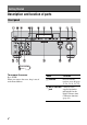
Getting Started Description and location of parts Front panel To remove the cover Press PUSH. When you remove the cover, keep it out of reach from children. Name Function A POWER Press to turn the receiver on or off (page 37, 50, 51, 52, 53, 79). B AUTO CAL MIC Connects to the jack supplied optimizer microphone for the Digital Cinema Auto Calibration function (page 41).
Function Name Function Adjusts FRONT BASS and FRONT TREBLE. Press TONE MODE repeatedly to select BASS or TREBLE, then turn TONE to adjust the level (page 59). K HDMI Press to select input source from the component connected to the HDMI IN jack (page 25). L PHONES jack Connects to headphones (page 75). TONE D Remote sensor Receives signals from remote commander. E MEMORY/ ENTER Press to operate a tuner (FM/AM/XM) (page TUNING MODE 80, 85).
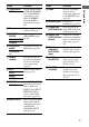
About the indicators on the display Name Function Name Function A SW Lights up when sub woofer selection is set to “YES” and the audio signal is output from the SUB WOOFER jack (page 66). While this indicator lights up, the receiver creates a sub woofer signal based on the L.F.E. signal in the disc being played back or the low frequency components of the front channels. B Playback channel indicators The letters (L, C, R, etc.) indicate the channels being played back.
Name Function D INPUT Lights up constantly. One of the input indicators also lights up according to the current input. E AUTO Lights up when INPUT MODE is set to “AUTO” (page 91). F HDMI 1 2 Lights up when the receiver recognizes a component connected via an HDMI IN jack (page 25). G DTS (-ES) Lights up when the receiver is decoding DTS signals. When the receiver is decoding DTS-ES signals, “DTS-ES” also lights up.
Name Function Name Function Q CAT Lights up when “ALL CATEGORY” mode is changed to “ONE CATEGORY” mode during XM Radio operation (page 85). V NEO:6 Lights up when DTS Neo:6 Cinema/Music decoding is activated (page 73). R ZONE 2 Lights up while operation in zone 2 is being enabled. X MATRIX S SLEEP Lights up when the sleep timer is activated (page 96). T L.F.E. Lights up when the disc being played back contains an L.F.E. (Low Frequency Effect) channel and the L.F.E.
Rear panel Getting Started A AUDIO INPUT/OUTPUT section L C ANTENNA section AUDIO IN/ OUT jacks Connects to a tape deck, MD deck or DAT player, etc (page 19, 23). FM ANTENNA Connects to the FM jack wire antenna (aerial) supplied with this receiver (page 36). MULTI CHANNEL INPUT jacks Connects to a Super Audio CD player or DVD player with an analog audio jack for 7.1 channel or 5.1 channel sound (page 19, 22).
E VIDEO/AUDIO INPUT/OUTPUT section L AUDIO IN/ OUT jacks R Connects to a VCR or a DVD player etc. (page 27, 29, 30, 31, 32, 34). VIDEO IN/ OUT jacks* S VIDEO IN/ OUT jacks* F SPEAKERS section Connects to speakers (page 17). * You can watch the selected input image when you connect the MONITOR OUT jack to a TV (page 27). You can also display certain menu settings and the sound field on the monitor when you press ON SCREEN on the remote (page 89).
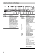
Remote commander Function A AV ?/1 Press to turn on or off the audio/ (on/standby) video components that the remote is assigned to operate (page 104). If you press the ?/1 (B) at the same time, it will turn off the receiver and other Sony components (SYSTEM STANDBY). Note The function of the AV ?/1 switch changes automatically each time you press the input button (C). RM-AAL003 B ?/1 Press to turn the receiver on or (on/standby) off.
Name Function Name Function H Numeric buttons Press to – preset/tune to preset stations. – select track numbers of the CD player, DVD player or MD deck. Press 0/10 to select track number 10. – select channel numbers of the VCR or satellite tuner. – After pressing TV (wj), press the numeric buttons to select the TV channels. P PRESET + b)/– Press to register FM/AM/XM Radio stations or to select preset stations.
Function T MASTER VOL +/– Press to adjust the volume level of all speakers at the same time (page 48). TV VOL +/– Press TV (wj) and then press TV VOL +/– to adjust the volume level of the TV. U DISC SKIP Press to skip a disc when using a multi-disc changer. V RETURN/ EXIT O Press to return to the previous menu or exit the menu while the menu or on-screen guide of the VCR, DVD player, or satellite tuner is displayed on the TV screen (page 103).
1: Installing speakers This receiver allows you to use a 7.1 channel system (7 speakers and one sub woofer). Enjoying a 5.1/7.1 channel system To fully enjoy theater-like multi-channel surround sound requires five speakers (two front speakers, a center speaker, and two surround speakers) and a sub woofer (5.1 channel system). You can enjoy high fidelity reproduction of DVD software recorded sound in the Surround EX format if you connect one additional surround back speaker (6.
2: Connecting speakers G F A E D Getting Started H FRONT SPEAKERS B terminals a) B C B A A Monaural audio cord (not supplied) B Speaker cords (not supplied) AFront speaker A (L) BFront speaker A (R) CCenter speaker DSurround speaker (L) ESurround speaker (R) FSurround back speaker (L)b) GSurround back speaker (R)b) HSub wooferc) a) If you have an additional front speaker system, connect them to the FRONT SPEAKERS B terminals.
c) When you connect a sub woofer with an auto standby function, turn off the function when watching movies. If the auto standby function is set to on, it turns to standby mode automatically based on the level of the input signal to a sub woofer, then sound may not be output. Note When you connect all the speakers with a nominal impedance of 8 ohms or higher, set “SP. IMPEDANCE” in the System Settings menu to “8 ohm.” In other connections, set it to “4 ohm.
3a: Connecting the audio components Audio input/output jacks to be connected This section describes how to hook up your components to this receiver. Before you begin, refer to “Component to be connected” below for the pages which describe how to connect each component. After hooking up all your components, proceed to “4: Connecting the antennas (aerials)” (page 36).
Connecting components with digital audio input/output jacks The following illustration shows how to connect a Super Audio CD player, CD player and an MD/DAT deck.
Notes on playing a Super Audio CD on a Super Audio CD player Getting Started • No sound is output when playing a Super Audio CD on a Super Audio CD player connected to only the COAXIAL SA-CD/ CD IN jacks on this receiver. When you play a Super Audio CD, connect the player to the MULTI CHANNEL INPUT or SA-CD/CD IN jacks. Refer to the operating instructions supplied with the Super Audio CD player. • You cannot make digital recordings of a Super Audio CD. Use the analog jack for recording in this case.
Connecting components with multi-channel output jacks If your DVD or Super Audio CD player is equipped with multi-channel output jacks, you can connect it to the MULTI CHANNEL INPUT jacks of this receiver to enjoy multichannel sound. Alternatively, the multichannel input jacks can be used to connect an external multi-channel decoder. DVD player, Super Audio CD player, etc.
Getting Started Connecting components with analog audio jacks The following illustration shows how to connect a component with analog jacks, such as tape deck, turntable, etc. Super Audio CD player, CD player Tape deck A A A A MD deck, DAT deck Turntable A Audio cord (not supplied) Note If your turntable has a ground (earth) wire, connect it to the (U) SIGNAL GND terminal.
3b: Connecting the video components How to hook up your components Video input/output jacks to be connected This section describes how to hook up your components to this receiver. Before you begin, refer to “Component to be connected” below for the pages which describe how to connect each component. After hooking up all your components, proceed to “4: Connecting the antennas (aerials)” (page 36).
HDMI features HDMI is the abbreviated name for HighDefinition Multimedia Interface. It is an interface which transmits video and audio signals in digital format. DVD player Audio/video signals • A digital audio signals transmitted by HDMI can be output from the speakers and the PRE OUT jacks on this receiver. This signal supports Dolby Digital, DTS, and linear PCM. • Analog video signals input to the VIDEO jack, S VIDEO jacks, or COMPONENT VIDEO jacks can be output as HDMI signals.
Notes on HDMI connections • Use an HDMI cable with the HDMI logo (made by Sony). • Check the setup of the connected component if an image is poor or the sound does not come out of a component connected via the HDMI cable. • An audio signal input to the HDMI IN jack is output from the speaker output terminals, HDMI OUT jack and PRE OUT jacks. It is not output from any other audio jacks. • Video signals input to the HDMI IN jack can only be output from the HDMI OUT jack.
Connecting a TV monitor Getting Started The image from a visual component connected to this receiver and the menu of this receiver can be displayed on a TV screen. It is not necessary to connect all the cables. Connect audio and video cords according to the jacks of your components.
Notes • Connect image display components such as a TV monitor or a projector to the MONITOR OUT jack on the receiver. You may not be able to record, even if you connect recording components. • Turn on the receiver when the video and audio of a playback component are being output to a TV via the receiver. If the power supply of the receiver is not turned on, neither video nor audio is transmitted.
The following illustration shows how to connect a DVD player/DVD recorder. It is not necessary to connect all the cables. Connect audio and video cords according to the jacks of your components. Note To output multi-channel digital audio, set the digital audio output setting on the DVD player. Refer to the operating instructions supplied with the DVD player.
Connecting a DVD recorder DVD recorder Audio signals A Video signals B A Optical digital cord (not supplied) B Audio cord (not supplied) C Video cord (not supplied) D S video cord (not supplied) 30GB C D
Connecting a satellite tuner Getting Started The following illustration shows how to connect a satellite tuner. It is not necessary to connect all the cables. Connect audio and video cords according to the jacks of your components.
Connecting components with analog video and audio jack The following illustration shows how to connect a component which has analog jacks such as a VCR, etc. It is not necessary to connect all the cables. Connect audio and video cords according to the jacks of your components.
This receiver is equipped with a function for converting video signals. You can output the video signal after connecting this receiver via the MONITOR OUT jack as shown in the illustration. • Video signals can be output as HDMI video, component video and S video signals. • S video signals can be output as HDMI video, component video and video signals. • Component video signals can be output as HDMI video, S video and video signals.
Notes on converting video signals Closed Caption display • You can convert only 480i component video signals into HDMI signals, S video signals, or video signals. Signals are converted from 480i interlace scanning to 480p progressive scanning, then the signals are output. • When video or S video signals from a VCR, etc.
Getting Started In the video input/output conversion table classified by the menu settings You can set the video signal conversion function on/off. The relationships between the video input and output signals set by “VIDEO CONVERT” and “PROGRESSIVE OUT” in the Video Settings menu are shown in the chart below.
4: Connecting the antennas (aerials) Connect the supplied AM loop antenna (aerial) and FM wire antenna (aerial). FM wire antenna (aerial) (supplied) AM loop antenna (aerial) (supplied) * The shape of the connector varies depending on the area. Notes • To prevent noise pickup, keep the AM loop antenna (aerial) away from the receiver and other components. • Be sure to fully extend the FM wire antenna (aerial). • After connecting the FM wire antenna (aerial), keep it as horizontal as possible.
Connecting the AC power cord (mains lead) Connect the supplied AC power cord (mains lead) to the AC IN terminal on the receiver, then connect the AC power cord (mains lead) to a wall outlet. AC OUTLET* AC IN terminal Performing initial setup operations Before using the receiver for the first time, initialize the receiver by performing the following procedure. This procedure can also be used to return settings you have made to their factory defaults. 1,2 2,3 1 Press POWER to turn off the receiver.
Inserting batteries into the remote Insert two R6 (size-AA) batteries in the RMAAL003 remote commander. Observe the correct polarity when installing batteries. RM-AAL003 Notes • Do not leave the remote in an extremely hot or humid place. • Do not use a new battery with old ones. • Do not mix manganese batteries and other kinds of batteries. • Do not expose the remote sensor to direct sunlight or lighting apparatuses. Doing so may cause a malfunction.
To switch the command mode of the RM-AAL003 remote 6: Setting the speakers Setting the speaker impedance Set the appropriate speaker impedance for the speakers you are using. 1 2 2 3 1 Press ?/1 while pressing RM SET UP. The RM SET UP button flashes. 2 4-6 Press 1 or 2 while the RM SET UP button is flashing. When you press 1, the command mode is set to AV SYSTEM 1. When you press 2, the command mode is set to AV SYSTEM 2. 3 Press ENTER when the RM SET UP button lights up.
6 7 Press V/v repeatedly to select “4 ohm” or “8 ohm” depending on the speakers you are using, then press to enter the selection. Press MENU to exit the menu. Press SPEAKERS (OFF/A/B/A+B) repeatedly to select the front speaker system you want to drive. Note You cannot switch the front speakers by pressing SPEAKER (OFF/A/B/A+B) when the headphones are connected to the receiver. Notes • If you are not sure of the impedances of the speakers, refer to the operating instructions supplied with your speakers.
Notes CALIBRATION) Optimizer microphone The DCAC (Digital Cinema Auto Calibration) function allows you to perform automatic calibration, such as checking the connection between each speaker and the receiver, adjusting the speaker level, and measuring the distance of each speaker from your listening position automatically. Refer also to the “Quick Setup Guide” supplied with the receiver.
Note Depending on the characteristics of the sub woofer you are using, the setup distance value may be further away from the actual position. 1 3 Using the receiver as a preamplifier You can use the auto calibration function when you use the receiver as a pre-amplifier. In this case, the distance value shown on the display may differ from the actual distance value. However, there will be no problems even if you continue to use the receiver with that value.
6 8 Press V/v repeatedly to select the parameter, then press to enter the selection. Calibration type Explanation ENGINEER Sets the frequency characteristics to a set that matches that of the Sony listening room standard. FULL FLAT Makes the measurement of frequency from each speaker flat. FRONT REF Adjusts the characteristics of all the speakers to match the characteristics of the front speaker. Press V/v repeatedly to select “AUTO CAL START,” then press to start the measurement.
Confirming/saving the measurement results 1 Confirm the measurement result. When the measurement ends, a beep sounds and the measurement result appears on the display. Measurement Display result 2 Explanation When the measurement process completes properly COMPLETE Proceed to step 2. When the measurement process fails ERROR CODE XX Item Explanation DIST.INFO Displays the measurement result for speaker distance. LEVEL INFO Displays the measurement result for speaker level.
Cause and remedies Warning code Explanation CODE 33 (SR) • Either the left or right surround speakers is not connected. • Surround back speakers are connected even though surround speakers are not connected. Connect the surround speaker to the SURROUND terminal. WARNING 41 The sound input from the optimizer microphone is outside the acceptable range. It is louder than the loudest sound that can be measured.
Display Explanation IN-PHASE The speaker is in phase. OUT-OFPHASE The speaker is out of phase. The “+” and “–” terminals of the speaker may be connected the other way around. However, depending on the speakers, “OUT-OF-PHASE” appears on the display even though the speakers are connected properly. This is because of the speakers’ specifications. In this case, you can continue to use the receiver. ---------- No speakers are connected.
x A.CAL LOAD? (Loads a preset measurement) Getting Started • PRESET-1 Loads the measurement value stored as “PRESET-1.” • PRESET-2 Loads the measurement value stored as “PRESET-2.” • PRESET-3 Loads the measurement value stored as “PRESET-3.” • OFF Select this when you do not want to load a preset value. x A.CAL SAVE? (Saves the measurement value) • PRESET-1 Saves the measurement results as “PRESET-1.” • PRESET-2 Saves the measurement results as “PRESET-2.
Playback Selecting a component 1 1 Selected input Components that can be played back VIDEO 1, 2 VCR, etc., connected to the VIDEO 1 or VIDEO 2 jack VIDEO 3 Video camera and TV game, etc., connected to the VIDEO 3 jack DVD DVD player, etc., connected to DVD jack TV/SAT Satellite tuner, etc., connected to the TV/SAT jack TAPE/CD-R Tape deck, etc., connected to the TAPE jack MD/DAT MD or DAT deck, etc., connected to the MD/DAT jack SA-CD/CD Super Audio CD or CD player, etc.
To activate the muting function Playback Press MUTING on the remote. To cancel, press MUTING on the remote again or turn MASTER VOLUME clockwise to raise the volume. Even if you turn off the receiver, the muting function works when you turn the receiver on again. To avoid damaging your speakers Before you turn off the receiver, be sure to turn down the volume level.
Listening to a Super Audio CD/CD 2 3 5 3 5 • The operation is described for a Sony Super Audio CD player. • Refer to the operating instructions supplied with the Super Audio CD player or CD player. 1 Turn on the Super Audio CD player or CD player, then place the disc in the tray. 2 3 Turn on the receiver. You can also use INPUT SELECTOR on the receiver to select “SA-CD/CD.” z You can select the sound field to suit the music. Refer to page 74 for details.
Watching a DVD Playback 2 3 7 3 MULTI CHANNEL DECODING lamp 7 • Refer to the operating instructions supplied with the TV and DVD player. z 1 2 3 Turn on the TV and DVD player. Turn on the receiver. Press DVD. Select the sound format of the disc to be played, if necessary. You can also use INPUT SELECTOR on this receiver to select “DVD.” z An example of the display You can select the sound field to suit the movie or the music. Refer to page 74 for details.
Enjoying video games 2 3 7 3 7 • Refer to the operating instructions supplied with the TV and video game. VIDEO 3 IN/PORTABLE AV IN 1 2 3 Turn on the TV and video game. Turn on the receiver. Press VIDEO 3*. You can also use INPUT SELECTOR on this receiver to select “VIDEO 3*.” * When you connect a TV game to the VIDEO 3 IN/PORTABLE AV IN jack on the front panel. An example of the display 52GB 4 Switch the input of the TV so that an image of the video game is displayed. 5 6 Set up the video game.
Watching video Playback 2 3 6 3 6 • Refer to the operating instructions supplied with the TV and VCR. 1 2 3 Turn on the VCR. Turn on the receiver. Press VIDEO 1*. You can also use INPUT SELECTOR on this receiver to select “VIDEO 1*.” * When you connect VCR to the VIDEO 1 jack. An example of the display 4 Switch the input of the TV so that an image of the VCR is displayed. 5 6 7 Play back the tape on the VCR. Adjust to a suitable volume.
To return to the previous display Amplifier Operations Press RETURN/EXIT O. Navigating through menus To exit the menu Press MENU. By using the amplifier menus, you can make various adjustments to customize the receiver. 1 3-6 RETURN/ EXIT O 1 2 Press RECEIVER. Receiver operation is enabled. 2 Press MENU. The list of setting menus appears. 3 Press V/v repeatedly to select the menu you want. 4 5 Press to enter the menu. Press V/v repeatedly to select the parameter you want to adjust.
Overview of the menus The following options are available in each menu. For details on navigating through menus, see page 54. Item Parameter Initial setting Refer page 1-Level Settings TEST TONE [xxxxxxxx] OFF, AUTO, FIX OFF page 58 - 59 PHASE NOISE [xxxxxxx] OFF, L/C, C/R, R/SL, R/SR, SR/SL, OFF SR/SBR, SBR/SBL, SBL/SL, SL/L, L/ SR PHASE AUDIO [xxxxxxx] OFF, L/C, C/R, R/SL, R/SR, SR/SL, OFF SR/SBR, SBR/SBL, SBL/SL, SL/L, L/ SR FRONT BAL. [xxx.x dB] R+20.0dB to L+20.0dB (0.
Menu Item Parameter 3-Sur Settings SOUND FIELD SELECT ? 4-Tuner Settings 5-Audio Settings 6-Video Settings Refer page A.F.D. AUTO page 72 page 61 - 62 SB DECODING [xxxx] OFF, AUTO, ON AUTO SB DEC MODE [xxxxxxx] DDEX, PLIIx MV, PLIIx MS PLIIx MV EFFECT LEVEL [xxx%] 20% to 120% (5% step) 100% CENTER WIDTH [x] 8 step 3 DIMENSION [xxxxxxx] FRONT +3 to SUR +3 0 PANORAMA MODE [xxx] OFF, ON OFF SCREEN DEPTH [xxx] ON, OFF ON VIR.
Menu Item Parameter Initial setting Refer page 7-Speaker Settings SUB WOOFER [xxx] NO, YES YES FRONT SP [xxxxx] SMALL, LARGE LARGE page 66 - 70 CENTER SP [xxxxx] MIX, NO, SMALL, LARGE LARGE 9-Auto Calibration LARGE SUR BACK SP [xxxxxx] BI-AMP, ZONE 2, NO, SINGLE, DUAL DUAL FRONT L xxfeet* 3feet to 22feet (1 foot** step) 9feet FRONT R xxfeet* 3feet to 22feet (1 foot** step) 9feet CENTER xxfeet* 3feet to 22feet (1 foot** step) 9feet SURROUND L xxfeet* 3feet to 22feet (1 foot** st
Adjusting the level (Level x CENTER (Center speaker level) Settings menu) x SURROUND L (Surround speaker (L) level) You can use the Level Settings menu to adjust the balance and level of each speaker. These settings are applied to all sound fields. Select “Level Settings” in the setting menus. For details on adjusting the parameters, see “Navigating through menus” (page 54) and “Overview of the menus” (page 55).
x D.RANGE COMP. (Dynamic range compressor) Tip Dynamic range compressor lets you compress the dynamic range of the soundtrack based on the dynamic range information included in the Dolby Digital signal. “STD” is the standard setting, but it only enacts light compression. Therefore, we recommend using the “MAX” setting. This greatly compresses the dynamic range and lets you view movies late at night at low volumes. Unlike analog limiters, the levels are predetermined and provide a very natural compression.
x CENTER BASS (Center speaker bass level) x CENTER TREBLE (Center speaker treble level) x SUR/SB BASS (Surround/surround back speaker bass level) x SUR/SB TREBLE (Surround/surround back speaker treble level) x PRESET x CLEAR (Equalizer preset clear) You can reset the adjusted equalizer settings to the initial setting. For details, see “Clearing stored equalizer settings.” To apply the stored equalizer 1 Perform steps 1 to 3 in “Navigating through menus” (page 54). Select “EQ Settings” in step 3.
Settings for the surround sound (Sur Settings menu) Sur Settings menu parameters x DIMENSION (Dimension control) Lets you perform further adjustments for Dolby Pro Logic II and IIx Music mode decoding. You can set this parameter only when A.F.D. mode is set to “PRO LOGIC II MUSIC” or “PRO LOGIC IIx MUSIC” (page 73). You can adjust the difference between the front channels and the surround channels.
e) x VIR.SPEAKERS (Virtual speakers) This parameter is provided especially for Cinema Studio EX modes (page 75). • ON Virtual speakers are created. • OFF Virtual speakers are not created. Using the surround back decoding mode (SB DECODING) By decoding the surround back signal of DVD software (etc.) recorded in Dolby Digital Surround EX, DTS-ES Matrix, DTS-ES Discrete 6.1, etc., format, you can enjoy the surround sound intended by the filmmakers. x SB DECODING • AUTO When the input stream contains the 6.
Notes Settings for the tuner (Tuner Settings menu) You can use the Tuner Settings menu to set the FM station receiving mode and to name preset stations. Select “Tuner Settings” in the Setting menus. For details on adjusting the parameters, see “Navigating through menus” (page 54) and “Overview of the menus” (page 55). Tuner Settings menu parameters x FM MODE (FM station receiving mode) • STEREO This receiver will decode the signal as stereo signal when the radio station is broadcast in stereo.
Settings for the audio (Audio Settings menu) You can use the Audio Settings menu to make settings for the audio to suit your preference. Select “Audio Settings” in the setting menus. For details on adjusting the parameters, see “Navigating through menus” (page 54) and “Overview of the menus” (page 55). Audio Settings menu parameters x DEC. PRIORITY (Digital audio input decoding priority) Lets you specify the input mode for the digital signal input to the DIGITAL IN and HDMI IN jacks.
Settings for the video (Video Settings menu) Video Settings menu parameters x COMPONENT V. ASSIGN? (Component Video Assign) Lets you reassign the component video input to another visual input. For details, see “Watching component images from other inputs (COMPONENT VIDEO ASSIGN)” (page 94). x HDMI VIDEO ASSIGN? (HDMI Video Assign) Lets you reassign the HDMI video input to another visual input. For details, see “Watching HDMI images from other inputs (HDMI VIDEO ASSIGN)” (page 93).
* Each video input can be adjusted independently for every INPUT SELECTOR. The adjusted value is held until the memory of this receiver is cleared. The adjusted value is retained, even if the power is turned off or the power cord (mains lead) is pulled out. x NAME IN? (Naming inputs) Lets you set the name of inputs selected. For details, see “Naming inputs” (page 90).
surround back speakers are also automatically set to “SMALL” (unless previously set to “NO”). x CENTER SP (Center speaker) x SURROUND SP (Surround speaker) The surround back speakers will be set to the same setting. • LARGE If you connect large speakers that will effectively reproduce bass frequencies, select “LARGE.” Normally, select “LARGE.” However, if the front speakers are set to “SMALL,” you cannot set the surround speakers to “LARGE.
bass frequencies output from that speaker, set it to “SMALL.” If the overall sound level is lower than you prefer, set all speakers to “LARGE.” If there is not enough bass, you can use the equalizer to boost the bass levels. For details, see “Adjusting the equalizer (EQ Settings menu)” (page 59).
x SP POSI. (Surround speaker position) Lets you specify the location of your surround speakers for proper implementation of the surround effects in the Cinema Studio EX modes (page 75). This setup item is not available when the surround speakers are set to “NO” (page 67). Amplifier Operations Also, the distance between the surround speakers/ surround back speakers and the listening position C cannot be more than 4.
Tip Surround speaker position is designed specifically for implementation of the Cinema Studio EX modes. For other sound fields, speaker position is not so critical. Those sound fields were designed under the premise that the surround speakers would be located behind the listening position, but presentation remains fairly consistent even with the surround speakers positioned at a rather wide angle.
Calibrating the appropriate settings automatically (Auto Calibration menu) Amplifier Operations For details, see “7: Calibrating the appropriate settings automatically (AUTO CALIBRATION)” (page 41).
Tips Enjoying Surround Sound Enjoying Dolby Digital and DTS surround sound (A.F.D. mode) The A.F.D. (Auto Format Direct) mode allows you to listen to higher fidelity sound and select the decoding mode for listening to a 2 channel stereo sound as multi-channel sound. • We usually recommend “A.F.D. AUTO,” however sometimes it may be better to use “SB DECODING” (page 62) to match the input stream to the mode you prefer. • You can identify the encoding format of DVD software, etc.
Type of A.F.D. mode Multi-channel audio after Effect decoding A.F.D. AUTO (Detecting automatically) Presets the sound as it was recorded/encoded without adding any surround effects. PRO LOGIC 4-channel signals Performs Dolby Pro Logic decoding. The source recorded in 2 channel format is decoded into 4.1 channels. PRO LOGIC II MOVIE 5-channel signals Performs Dolby Pro Logic II Movie mode decoding. This setting is ideal for movies encoded in Dolby Surround.
Selecting a preprogrammed sound field (DCS) You can take advantage of surround sound simply by selecting one of the receiver’s preprogrammed sound fields. They bring the exciting and powerful sound of movie theaters and concert halls into your home. • When one of the sound fields for music is selected, no sound is output from the sub woofer if all the speakers are set to “LARGE” in the System Settings menu. However, the sound will be output from the sub woofer if the digital input signal contains L.F.E.
Types of sound field available Sound field Effect Movie CINEMA STUDIO EX A DCS Reproduces the sound characteristics of the Sony Pictures Entertainment “Cary Grant Theater” cinema production studio. This is a standard mode, great for watching almost any type of movie. CINEMA STUDIO EX B DCS Reproduces the sound characteristics of the Sony Pictures Entertainment “Kim Novak Theater” cinema production studio. This mode is ideal for watching science-fiction or action movies with lots of sound effects.
Using only the front speakers (2CH STEREO) In this mode, the receiver outputs the sound from the front left/right speakers only. There is no sound from the sub woofer. Standard 2 channel stereo sources completely bypass the sound field processing and multichannel surround formats are downmixed to 2 channel. Enjoying the surround effect at low volume levels (NIGHT MODE) This function allows you to retain a theater like environment at low volume levels. This function can be used with other sound fields.
Notes • This function does not work in following cases. – MULTI IN is selected. – Input signals of which the sampling frequency is more than 96 kHz are being received. • If you set the NIGHT MODE to on during DTS 96/ 24 signal reception, it will play back only at 48 kHz. Tip While this function is on, the BASS, TREBLE, and EFFECT levels increase, and “D.RANGE COMP.” is automatically set to “MAX” (page 59).
Adjusting the speaker levels and balance (TEST TONE) You can adjust the speaker levels and balance while listening the test tone from your listening position. 5 Press V/v repeatedly to select “Level Settings,” then press to enter. 6 Press V/v repeatedly to select “TEST TONE,” then press . 7 Press V. The test tone is output from each speaker in sequence. Also, if you press v, the pattern will become the “FIX” pattern in which the test tone is output from the selected speaker only.
When a test tone is not output from the speakers • The speaker cords may not be connected securely. Check to see if they are connected securely and cannot be disconnected by pulling on them slightly. • The speaker cords may have the short-circuit problem.
Tuner Operations Listening to FM/AM radio You can listen to FM and AM broadcasts through the built-in tuner. Before operation, make sure you have connected the FM and AM antennas (aerials) to the receiver (page 36). Tip The tuning scale for direct tuning is shown below. • FM band 100 kHz • AM band 10 kHz* * The AM tuning scale can be changed (page 120). Automatic tuning 1 2 1 Press TUNER repeatedly to select the FM or AM band. 2 Press TUNING +/–.
Presetting radio stations Direct tuning Enter the frequency of a station directly by using the numeric buttons. You can preset up to 30 FM and 30 AM stations. Then you can easily tune in the stations you often listen to. 1 Presetting radio stations 1 3 2 4 Press TUNER repeatedly to select the FM or AM band. 2 3 Press D.TUNING. 3,5 Press the numeric buttons to enter the frequency. Example 1: FM 102.50 MHz Select 1 b 0 b 2 b 5 b 0 Example 2: AM 1,350 kHz Select 1 b 3 b 5 b 0 4 Press ENTER.
3 4 Press MEMORY. 1 “MEMORY” appears on the display for a few seconds. Perform steps 4 and 5 before the display goes out. Press TUNER repeatedly to select the FM or AM band. 2 Press PRESET +/– repeatedly to select the preset station you want. Press PRESET +/– to select a preset number. Each time you press the button, you can select a preset station as follows: • AM band: AM1 to AM30 • FM band: FM1 to FM30 You can also press the numeric buttons to select the preset station you want.
2 3 Tune in the preset station you want to create an index name for (page 82). Press RECEIVER. Receiver operation is enabled. 4 Press MENU. The list of setting menus appears. Press V/v repeatedly to select “Tuner Settings,” then press . 6 Press V/v repeatedly to select “NAME IN?.” 7 Press to enter the parameter. The cursor flashes and you can select a character. Follow the procedure given in “Naming inputs” (page 90). XM Radio is the satellite radio service with millions of listeners across the U.
Notes • To ensure optimal reception of XM’s satellite signal, move your antenna to various window locations around your home to see where the best reception will be received. Most XM customers place the antenna in a south-facing window with a clear view to the sky. • Residents in Canada, please see information about XM Canada at the following webpage or number: (http://www.xmradio.
Receiving XM Radio broadcasts 1 Selecting channels from a category (CATEGORY TUNING) You can select a channel from one category or all the categories by changing the category mode. 1 3 1 Press TUNER repeatedly to select “XM RADIO.” 2 2 Press TUNING +/– to select a channel. 4 You can also press TUNING MODE on the receiver to select “AUTO,” and then turn TUNING to select a channel. Tuner Operations 2 1 Press TUNER repeatedly to select “XM RADIO.
4 Press TUNING +/– to select the channel. You can also press TUNING MODE on the receiver to select “AUTO,” and then turn TUNING to select the channel. Displaying the XM-Radio information on the display Notes • When you select a channel in the “ONE CATEGORY” mode, the channel you selected may not be the one in the category you want. This is because one channel may belong to more than one category.
4 Presetting XM Radio stations You can select the channels you want directly by presetting them using the preset numbers. You can preset up to 30 XM Radio channels. Presetting channels using the preset numbers 1 Press PRESET +/– to select the preset number. You can also select the number by pressing the numeric buttons. Preset numbers from 1 to 30 are available, and channel 1 is preset for all the preset numbers when you purchase the receiver. 5 6 Press ENTER.
2 Press PRESET +/– repeatedly to select the preset channel you want. You can also press the numeric buttons to select the preset channel you want. Then press ENTER to enter the selection. You can select preset stored preset channels from 1 to 30. Note The preset channel information will be updated depending on the service provided by the XM Satellite Radio Inc. that you have subscribed to.
4 The following menus are displayed on the TV screen. 1-Level Settings 2-Equalizer Settings 3-Surround Settings 4-Tuner Settings 5-Audio Settings 6-Video Settings 7-Speaker Settings 8-System Settings 9-Auto Calibration Other Operations Displaying menus of the receiver on the TV screen Press ON SCREEN, then display a menu on the TV screen connected to this receiver. You can set up menus easily. 1 3 Press MENU. 5 Press V/v repeatedly to select the menu item, then press to enter the menu.
4 Press V/v repeatedly to select “Tuner Settings,” “Audio Settings,” “Video Settings,” or “Auto Calibration.” 5 6 Press Naming inputs You can enter a name of up to 8 characters for inputs and display it on the receiver’s display. This is convenient for labeling the jacks with the names of the connected components. to enter the menu. Press V/v repeatedly to select “NAME IN ?” or “A.CAL NAME?,” then press to enter. The cursor flashes and you can select a character.
2 Switching between digital and analog audio (INPUT MODE) When you connect components to both digital and analog audio input jacks on the receiver, you can fix the audio input mode to either of them, or switch from one to the other, depending on the type of material you intend to watch. 1 2 Press RECEIVER. Receiver operation is enabled. 3 Press INPUT MODE repeatedly to select the audio input mode. The selected audio input mode appears on the display.
Listening to digital sound from other inputs (DIGITAL ASSIGN) You can reassign digital audio input that has OPTICAL or COAXIAL (VIDEO 1 IN, DVD IN, TV/SAT IN, MD/DAT IN, SA-CD/CD IN) signals to another input (VIDEO 2 etc.) when they are not currently being used. For example, to make the DVD player the sound source for the digital audio input using the OPTICAL IN jack on the receiver, then: • Connect the optical output jack of the DVD player and the OPTICAL VIDEO 2 IN jack of the receiver.
Digital audio input Assignable inputs TAPE/CD-R COAX TAPE/CD-R, VIDEO 1, VIDEO 2, VIDEO 3, TV/SAT, MD/DAT SA-CD/CD COAX SA-CD/CD, VIDEO 1, VIDEO 2, VIDEO 3, TV/SAT, MD/DAT Notes • You cannot reassign more than one digital audio input to the same input. • You cannot assign optical signals from an input source to the optical input jacks on the receiver, and you cannot assign coaxial signals from the input source to the coaxial input jacks on the receiver.
6 7 8 Press . Press V/v repeatedly to select the input you want to assign as an HDMI video input selected in step 5. Press . The input you can assign varies for each component video input. For details, see “Assignable inputs for an HDMI video input.” Watching component images from other inputs (COMPONENT VIDEO ASSIGN) You can reassign a component video input to another input (VIDEO 2 IN etc.).
5 6 7 8 Press V/v repeatedly to select an input (DVD in the example) you want to reassign. Changing the display Press You can check the sound field, etc., by changing the information on the display. . Press V/v repeatedly to select the input (SA-CD/CD in the example) you want to assign as the component video input selected in step 5. Press DISPLAY . If an input is switched to “SA-CD/CD,” the image from the DVD player will be a component image.
Using the Sleep Timer You can set the receiver to turn off automatically at a specified time. Recording using the receiver You can record from a video/audio component using the receiver. Refer to the operating instructions supplied with your recording component. SLEEP 1 Press SLEEP repeatedly. Each time you press SLEEP, the display changes cyclically as follows: Recording onto a MiniDisc or audio tape When Sleep Timer is being used, “SLEEP” lights up on the display.
Notes • Sound adjustments do not affect the signal output from the TAPE/CD-R OUT or MD/DAT OUT jacks. • The audio signals input to the MULTI CHANNEL INPUT jacks are output only from the front left/ right channels. To record digital sound Connect a component for playback to the digital audio input (OPTICAL IN) jack, and connect the recording component to the OPTICAL MD/DAT OUT jack. Recording onto recording media 1 Press the input button of the playback component.
Listening to the sound in another zone (Zone 2 operations) You can enjoy images and sounds from a component connected to the receiver in a zone (zone 2) other than the main zone. For example, you can listen to the CD in the main zone and watch the DVD in zone 2. When using an IR repeater (not supplied), you can also operate both a component in the main zone and a Sony receiver in zone 2 from zone 2. Use the RM-AAL003 remote for the operation. • Switching the output source for the ZONE 2 OUT jacks.
2 Outputs sound from speakers in zone 2 using the receiver and another amplifier. Main zone Zone 2 STR-DG1000 E A C TV monitor E B D C ZONE 2 VIDEO OUT ZONE 2 AUDIO OUT RM-AAL003 Other Operations A Audio component B Video component C IR repeater (not supplied) D Sony’s Amplifier/Receiver E Speaker Notes • Connect video signals to the component of zone 2 using the VIDEO jack. • Connect audio signals to the component of zone 2 using the AUDIO L/R jack.
The following operations are described for connecting an IR repeater and operating the receiver in zone 2. When an IR repeater is not connected, use this receiver in the main zone. 4 2 4 Press one of the input buttons on the remote to select the source signals you want to output. For zone 2, analog video and audio signals are output. When you select “SOURCE,” the signals of the current input selected in the main zone are output. 5 Adjust to a suitable volume.
To operate the receiver using an IR repeater You can operate the receiver without pointing the remote toward the IR sensor of the receiver if you use an IR repeater. Use an IR repeater when you install the receiver in a place where signals from the remote cannot reach. Using a bi-amplifier connection If you are not using surround back speakers, you can use the SURROUND BACK SPEAKERS terminals for the front speakers for use with a bi-amplifier connection.
Notes • You cannot use the FRONT SPEAKERS B terminals for a bi-amplifier connection. • When you use the auto calibration function, make the bi-amplifier settings before you perform auto calibration. • If you make the bi-amplifier settings, the speaker level, balance, and equalizer settings of the surround back speakers become invalid, and those of the front speakers are used. • Signals output from the PRE OUT jacks are used with the same settings as those of the SPEAKERS terminals.
Using the Remote Operating each component using the remote When you program the remote to control the following Sony or non-Sony components, you can use the buttons on the remote that are marked with circles. Note, however, that some buttons may not operate your component. If you want to change the contents of the input list to match your particular components, see “Programming the remote,” on page 104.
1 Programming the remote Press AV ?/1 while pressing RM SET UP. The RM SET UP button flashes. You can customize the remote to match the components connected to your receiver. You can even program the remote to control nonSony components and also Sony components that the remote is normally unable to control. The procedure below uses as an example a case in which the other manufacturer’s VCR is connected to the VIDEO 2 jacks on the receiver.
The numeric codes corresponding to the component and the maker of the component Use the numeric codes in the tables below to control non-Sony components and also Sony components that the remote is normally unable to control. Since the remote signal that a component accepts differs depending on the model and year of the component, more than one numeric code may be assigned to a component. If you fail to program your remote using one of the codes, try using other codes.
To control a VCR To control a DVD recorder Maker Code(s) Maker Code(s) SONY 701, 702, 703, 704, 705, 706 SONY 403 AIWA* 710, 750, 757, 758 To control a TV AKAI 707, 708, 709, 759 BLAUPUNKT 740 EMERSON 711, 712, 713, 714, 715, 716, 750 FISHER 717, 718, 719, 720 GENERAL ELECTRIC 721, 722, 730 GOLDSTAR/LG 723, 753 Maker Code(s) SONY 501, 502 DAEWOO 504, 505, 506, 507, 515, 544 FISHER 508 GOLDSTAR/LG 503, 511, 512, 515, 534, 544 GRUNDIG 724 GRUNDIG 517, 534 HITACHI 722, 7
To control a satellite tuner or cable box Maker Code(s) SONY 801, 802, 803, 804 JERROLD/G.I. 806, 807, 808, 809, 810, 811, 812, 813, 814 PANASONIC 818 RCA 805, 819 S. ATLANTA 815, 816, 817 Performing several commands in sequence automatically (Macro Play) Maker Code(s) The Macro Play function lets you link several commands in a sequential order as a single command. The remote provides 2 macro lists (MACRO 1 and MACRO 2). You can specify up to 20 commands for each macro list.
Program the sequence of the operation 3 Press the button for the operation you want to perform to learn the function as follows. 1,5 Press Operations to be programmed 2,3 H, x, X, M, m, ., > Performs the operation of the button. The input Switches inputs. button for more than 1 second MACRO 1 or MACRO 2 Make a one second interval. When you want to make a longer interval, press MACRO 1 or MACRO 2 repeatedly. The input button selected in step 2 flashes twice, then lights up again.
Starting macro play 1 Press RECEIVER. The RECEIVER button lights up, and then turns off. 2 Press MACRO 1 or MACRO 2 to start the macro. The macro starts and execute the commands in the order you assigned them. While the commands are being sent, the RM SET UP button flashes and the RECEIVER button lights up. When the commands have been sent, the RM SET UP and RECEIVER buttons turn off.
4 Point the remote code receiver section of the remote toward the receiver/transmitter on the remote control to be learned from. While the second remote is receiving the signal, the input button selected in step 2 turns off. Using a command that has been learned When selecting a learned input, press the button used to learn that function. To erase the learned code 1 Press TV while pressing RM SET UP.
Clearing all the contents of the remote’s memory 1 Using the Remote 1,2 1 Press and hold MASTER VOL – first, then press ?/1 and then AV ?/1. The RM SET UP button flashes three times. 2 Release MASTER VOL –. All the contents of the remote’s memory (i.e., all the programmed data) are cleared.
x Crossover frequency Additional Information Glossary x Cinema Studio EX A surround sound mode that can be regarded as the compilation of Digital Cinema Sound technology, delivers the sound of a dubbing theater using three technologies: “Virtual Multi Dimensions,” “Screen Depth Matching,” and “Cinema Studio Reverberation.” “Virtual Multi Dimensions,” the virtual speaker technology, creates a virtual multisurround environment with actual speakers up to 7.
x Dolby Pro Logic IIx x DTS-ES Technology for 7.1 channels (or 6.1 channels) playback. Along with audio encoded in Dolby Digital Surround EX, 5.1 channels Dolby Digital encoded audio can be reproduced in 7.1 channels (or 6.1 channels). Furthermore, existing stereo recorded content can also be reproduced in 7.1 channels (or 6.1 channels). Format for 6.1 channels playback with surround back information. There are two modes, “Discrete 6.1” which records all channels independently, and “Matrix 6.
x PCM (Pulse Code Modulation) A method of converting analog audio to digital audio for easy enjoyment of digital sound. Precautions x Progressive On safety A scanning method that draws all scanning lines sequentially, as opposed to interlaced scanning where all the odd and then all the even lines are drawn. Should any solid object or liquid fall into the cabinet, unplug the receiver and have it checked by qualified personnel before operating it any further.
• Do not place the receiver near heat sources, or in a place subject to direct sunlight, excessive dust, or mechanical shock. • Do not place anything on top of the cabinet that might block the ventilation holes and cause malfunctions. • Do not place the receiver near equipment such as a television, VCR, or tape deck. (If the receiver is being used in combination with a television, VCR, or tape deck, and is placed too close to that equipment, noise may result, and picture quality may suffer.
There is no sound from one of the front speakers. • Connect a pair of headphones to the PHONES jack to verify that sound is output from the headphones. If only one channel is output from the headphones, the component may not be connected to the receiver correctly. Check that all the cords are fully inserted into the jacks on both the receiver and the component. If both channels are output from the headphones, the front speaker may not be connected to the receiver correctly.
There is no sound, or only a very lowlevel sound is heard from the center/ surround/surround back speakers. • Select a CINEMA STUDIO EX mode (page 75). • Adjust the speaker level (page 78). • Make sure the center/surround speaker (s) is (are) set to either “SMALL” or “LARGE” (page 67). • Make sure the surround back speakers are set to “DUAL” or “SINGLE” (page 67). There is no sound from the surround back speakers.
The image of the COMPONENT VIDEO OUT is corrupted. • When the signals are output from the COMPONENT VIDEO OUT jack, input signals other than 480p are corrupted if “PROGRESSIVE OUT” is set to “ON.” Set “PROGRESSIVE OUT” to “OFF.” • Video input signals other than 480p component are not received when signals are output from the S VIDEO jack or the VIDEO jack. Input 480i component video signals.
• Make sure you select the correct input on the remote. • When you operate a programmed nonSony component, the remote may not function properly depending on the model and the maker of the component. Error message If there is a malfunction, the display shows a code of two numbers and a message. You can check the condition of the system by the message. Refer to the following table to solve the problem. If any problem persists, consult your nearest Sony dealer.
Frequency response PHONO RIAA equalization curve ± 0.5 dB MULTI CHANNEL INPUT, SA-CD/CD, TAPE/CD-R, MD/DAT, DVD, VIDEO 1/2/3 10 Hz – 100 kHz ± 3 dB Inputs (Analog) PHONO Sensitivity: 2.5 mV Impedance: 50 kohms S/N: 86 dB (A, 20 kHz LPF) MULTI CHANNEL INPUT, SA-CD/CD, TAPE/CD-R, MD/DAT, DVD, TV/SAT, VIDEO1/2/3 Sensitivity: 150 mV Impedance: 50 kohms S/N: 96 dB (A, 20 kHz LPF) FM tuner section Tuning range 87.5 - 108.
Video section Inputs/Outputs Video: S video: 1 Vp-p, 75 ohms Y: 1 Vp-p, 75 ohms C: 0.286 Vp-p, 75 ohms COMPONENT VIDEO: Y: 1 Vp-p, 75 ohms PB/CB: 0.7 Vp-p, 75 ohms PR/CR: 0.7 Vp-p, 75 ohms 80 MHz HD Pass Through (When “PROGRESSIVE OUT” is set to “OFF”.) General Power requirements 120 V AC, 60 Hz Power consumption 480 W/580 VA Power consumption (during standby mode) 1W AC outlets 2 switched, 100 W/0.8 A MAX Dimensions 430 × 175 × 430 mm (17 × 7 × 17 in) including projecting parts and controls Mass (Approx.
Index Symbols U SIGNAL GND terminal 23, 36 Numerics 2CH STEREO mode 76 5.1 channel system 16 7.1 channel system 16 A A.F.D.
O TV ON SCREEN 78, 89 Connecting 27 R V Recording Onto a MiniDisc or audio tape 96 Onto a video tape 97 Remote All clear 111 Before use 38 Learning 109 Macro Play 107 Operating each component 103 Programming 104 Resetting 119 VCR Connecting 32 Playback 53 Video game 52 Video signal conversion 33 X XM Radio 83 Z ZONE 2 98 S Additional Information Satellite tuner 31 SB DEC MODE 62 SB DECODING 62 Sleep Timer 96 Sound fields Customizing 61 Resetting 79 Selecting 74 Speakers Connecting 17 Levels and