4-244-183-12(1) Home Theater System Operating Instructions Owner’s Record The model and serial numbers are located at the rear of the unit. Record the serial number in the space provided below. Refer to them whenever you call upon your Sony dealer regarding this product. Model No. Serial No.
WARNING To prevent fire or shock hazard, do not expose the unit to rain or moisture. To prevent fire, do not cover the ventilation of the apparatus with newspapers, table-cloths, curtains, etc. And don’t place lighted candles on the apparatus. To prevent fire or shock hazard, do not place objects filled with liquids, such as vases, on the apparatus. Don’t throw away the battery with general house waste, dispose of it correctly as chemical waste. – Reorient or relocate the receiving antenna.
Table of Contents List of Button Locations and Reference Pages Receiving Broadcasts Storing FM stations automatically (AUTOBETICAL)1) ...................... 28 Direct tuning ........................................ 28 Automatic tuning ................................. 29 Preset tuning ........................................ 29 Using the Radio Data System (RDS)1) .......................................... 31 Main unit ...............................................
About This Manual Note for the supplied remote The HT-DDW750 consists of: RM-PP412 – Receiver • Models of area code CEL, CEK only • Models of other area code – Front/surround speakers • Models of area code CEL, CEK only • Models of other area code – Center speakers • Models of area code CEL, CEK only • Models of other area code – Sub woofer • Models of area code U, CA only • Models of other area code The VIDEO3, TV/SAT, PHONO, AUX, MULTI CH, SOURCE, DIRECT, AAC BI-LING, SB DECODING, 12 and ON SCREEN bu
List of Button Locations and Reference Pages Illustration number Use this page to find the location of buttons that are mentioned in the text. DISPLAY 2 (21, 31, 46) R R Name of button/part Reference page Main unit M–O ALPHABETICAL ORDER A–L A.F.D.
Hooking Up the Components Required cords The following optional connection cords A – E are required when you hook up the components (pages 8 – 10). A Audio cord (not supplied) D Optical digital cord (not supplied) White (L) Red (R) E Coaxial digital cord (supplied) B Audio/video cord (not supplied) Orange Yellow (video) White (L/audio) Red (R/audio) C Video cord (not supplied) Yellow Before you get started • Turn off the power to all components before making any connections.
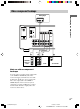
Antenna hookups Hooking Up the Components AM loop antenna (supplied) FM wire antenna (supplied) DIGITAL ANTENNA OPTICAL VIDEO 2 IN MONITOR AM y VIDEO IN VIDEO IN VIDEO OUT VIDEO IN VIDEO OUT FM 75Ω COAXIAL DVD IN COAXIAL L AUDIO OUT R IN CD IN OUT MD/TAPE AUDIO IN AUDIO IN AUDIO OUT AUDIO IN DVD VIDEO 2 VIDEO 1 SUB WOOFER * * The shape of the connector varies depending on the area code.
Audio component hookups MD or Tape deck INPUT OUTPUT LINE LINE L A A ç R ç OUT DIGITAL IN ANTENNA OPTICAL VIDEO 2 IN MONITOR AM y VIDEO IN VIDEO IN VIDEO OUT VIDEO IN VIDEO OUT FM 75Ω COAXIAL DVD IN COAXIAL L AUDIO OUT R IN OUT IN MD/TAPE CD AUDIO IN AUDIO IN AUDIO OUT AUDIO IN DVD VIDEO 2 VIDEO 1 SUB WOOFER A OUTPUT LINE L R CD player 8GB 01GB03HUPCA.
Video component hookups DVD player Hooking Up the Components OUTPUT AUDIO OUT L R VIDEO OUT B ANTENNA DIGITAL OPTICAL VIDEO 2 IN MONITOR AM y VIDEO IN VIDEO IN VIDEO OUT VIDEO IN VIDEO OUT FM 75Ω COAXIAL DVD IN COAXIAL L AUDIO OUT R AUDIO IN AUDIO IN AUDIO OUT AUDIO IN DVD VIDEO 2 Ç Ç OUT IN B B VIDEO 1 SUB WOOFER IN C B INPUT OUTPUT OUTPUT Satellite tuner or VCR IN OUT MD/TAPE Ç IN CD VIDEO OUT VIDEO IN VIDEO OUT AUDIO OUT AUDIO IN AUDIO OUT INPUT VIDEO IN L L R
Digital component hookups Connect the digital output jacks of your DVD player and satellite tuner (etc.) to the receiver’s digital input jacks to bring the multi channel surround sound of a movie theater into your home. To fully enjoy multi channel surround sound, five speakers (two front speakers, two surround speakers, and a center speaker) and a sub woofer are required. Note All the OPTICAL and COAXIAL jacks are compatible with 96 kHz, 48 kHz, 44.1 kHz and 32 kHz sampling frequencies.
Other hookups AC power cord L R R L FRONT SPEAKERS R CENTER L L Hooking Up the Components b To a wall outlet R SURROUND IMPEDANCE USE 8 – 16Ω Setting the voltage selector If your receiver has a voltage selector on the rear panel, check that the voltage selector is set to the local power supply voltage. If not, use a screwdriver to set the selector to the correct position before connecting the AC power cord to a wall outlet.
Hooking Up and Setting Up the Speaker System Speaker system hookups Required cords A Speaker cords (supplied) B Monaural audio cord (supplied) (+) Black (–) Active sub woofer Front speaker (R) Front speaker (L) E E INPUT e B b e A A To a wall outlet (Switch the power (POWER) to off before connecting the power cord.
Tip To prevent speaker vibration or movement while listening, attach the supplied foot pads at the bottom of the speakers. Notes • Connect the long speaker connecting cords to the surround speaker terminals and the short speaker connecting cords to the front and center speaker terminals. • Twist the stripped ends of the speaker cords about 10 mm (2/3 inch). Be sure to match the speaker cord to the appropriate terminal on the components: + to + and – to –.
Performing initial setup operations Once you have hooked up the speakers and turned on the power, clear the receiver’s memory. Then specify the speaker parameters (size, position, etc.) and perform any other initial setup operations necessary for your system. Tip To check the audio output during settings (to set up while outputting the sound), check the connection (page 19).
When placing surround speakers behind you (wide room) B Sub woofer A C Hooking Up and Setting Up the Speaker System To select “NORM. SP.”, turn off the power, then turn on again while pressing MAIN MENU. (To reset to “MICRO SP.”, do the same procedure.) A 45° C If you change the speaker system, select “NORM. SP.”. You can adjust the speaker size and sub woofer selection when you select “NORM. SP.” (page 17). Tip 90° The setting for Micro Satellite Speaker (MICRO SP.
Multi channel surround setup (continued) x Front speaker distance ( X.X m (XX ft.)) L R DIST. Set the distance from your listening position to the front speakers (A on page 14). x Center speaker distance ( X.X m (XX ft.)) C DIST. Set the distance from your listening position to the center speaker. Center speaker distance should be set from a distance equal to the front speaker distance (A on page 14) to a distance 1.5 meters (5 feet) closer to your listening position (B on page 14).
Tip Only when you use the speaker system other than the supplied one, be sure to set the following parameters. For details on “NORM. SP.” (Normal Speaker), see page 15. x Sub woofer selection ( SW S.W. XXX) • If you connect a sub woofer, select “YES”. • If you do not connect a sub woofer, select “NO”. This activates the bass redirection circuitry and outputs the LFE signals from other speakers.
Multi channel surround setup (continued) x Surround speaker size ( SL SR XXXXX) • If you connect large speakers that will effectively reproduce bass frequencies, select “LARGE”. Normally, select “LARGE”. However, if the front speakers are set to “SMALL”, you cannot set the surround speakers to “LARGE”.
Listening to the sub woofer Checking the connections POWER indicator POWER After connecting all of your components to the receiver, do the following to verify that the connections were made correctly. First, turn down the volume on the receiver. The volume should be set to minimum before you begin playing the program source. 1 Turn on the receiver and select the program source. Hooking Up and Setting Up the Speaker System 1 Press ?/1 to turn on the receiver.
Basic Operations Selecting the component Input Selector buttons Select To OPT IN Specify the digital audio signals input to the DIGITAL OPTICAL input jacks. ANALOG Specify the analog audio signals input to the AUDIO IN (L/R) jacks. Press the input selector button to select the component you want to use. To select Press Note VCR VIDEO 1 or VIDEO 2 Satellite tuner VIDEO 2 When the 96 kHz digital signal is input, the tone, sound field and surround effects do not function.
Changing the display DIMMER Press DIMMER repeatedly to adjust the brightness of the display (3 steps). However, when you press any button, the display becomes the brightest setting temporary.
Enjoying Surround Sound You can take advantage of surround sound simply by selecting one of the receiver’s preprogrammed sound fields. They bring the exciting and powerful sound of movie theaters and concert halls into your home. You can also customize the sound fields to obtain the sound you want by changing the surround parameter. To fully enjoy surround sound, you must register the number and location of you speakers.
Enjoying stereo sound in multi channel (Dolby Pro Logic ) This receiver incorporates with Dolby Pro Logic II which has movie mode and music mode, and the receiver can reproduce the 2 channel sound in 5.1 channel through Dolby Pro Logic II. Selecting a sound field You can enjoy surround sound simply by selecting one of the pre-programmed sound fields according to the program you want to listen to. Press To select MOVIE C.ST.EX A DCS* C.ST.EX B DCS* Press A.F.D.
Selecting a sound field (continued) Selecting other sound fields x C.ST.EX A (Cinema Studio EX A) Press MUSIC repeatedly to select the sound field you want. Reproduces the sound characteristics of the Sony Pictures Entertainment “Cary Grant Theater” cinema production studio. This is a standard mode, great for watching most any type of movie. x C.ST.EX B (Cinema Studio EX B) Reproduces the sound characteristics of the Sony Pictures Entertainment “Kim Novak Theater” cinema production studio.
Understanding the multi channel surround displays 1 2 3 SP L SW SL qs C R aDIGITAL OPT COAX 4 5 6 a PRO LOGIC II DTS D.RANGE STEREO MONO RDS MEMORY SLEEP LFE S SR q; 9 8 7 qa 2 SP: Lights up when you turn on the receiver. Note Does not light up when you connect headphones to the PHONES jack. 3 ; DIGITAL: Lights up when the receiver is decoding signals recorded in the Dolby Digital format.
Understanding the multi channel surround displays (continued) Adjusting the level parameters qs Playback channel indicators: The letters (L, C, R, etc.) indicate the channels being played back. The boxes around the letters vary to show how the receiver downmixes the source sound (based on the speakers settings). When using sound fields like “C.ST.EX”, the receiver adds reverberation based on the source sound. The LEVEL menu contains parameters that let you adjust the balance and volumes of each speaker.
Front balance ( L R BAL. L/R XX) Lets you adjust the balance between front left and right speakers. Center level (CTR XXX dB) Lets you adjust the level of the center speaker. Surround left level (SUR.L. XXX dB) Lets you adjust the level of the surround left speaker. Surround right level (SUR.R. XXX dB) Sub woofer level (S.W. XXX dB) Lets you adjust the level of the sub woofer. Dynamic range compressor ( COMP. XXX) D. RANGE Lets you compress the dynamic range of the sound track.
Receiving Broadcasts Notes Before receiving broadcasts, make sure you have connected FM and AM antennas to the receiver (page 7). Storing FM stations automatically (AUTOBETICAL) (Models of area code CEL, CEK only) This function lets you store up to 30 FM and FM RDS stations in alphabetical order without redundancy. Additionally, it only stores the stations with the clearest signals. If you want to store FM or AM stations one by one, see “Presetting radio stations” on page 30.
4 If you’ve tuned in an AM station, adjust the direction of the AM loop antenna for optimum reception. 5 Repeat steps 1 to 4 to receive another station. Tips The tuning scale differs depending on the area code as shown in the following table. For details on area codes, see page 4. Area code FM AM U, CA 100 kHz 10 kHz* CEL, CEK, SP, AU 50 kHz 9 kHz E2/E3 50 kHz 9 kHz* MX 50 kHz 10 kHz * The AM tuning scale can be changed (page 48).
Preset tuning (continued) Tuning to preset stations Presetting radio stations You can tune the preset stations by either of the following two ways. Scanning the preset stations 1 Press TUNER FM/AM. The last received station is tuned in. 2 Tune in the station that you want to preset using Direct Tuning (page 28) or Automatic Tuning (page 29). 3 Press MEMORY. “MEMORY” appears in the display for a few seconds. Do steps 4 to 5 before “MEMORY” goes out.
Using the Radio Data System (RDS) (Models of area code CEL, CEK only) This receiver also allows you to use RDS (Radio Data System), which enables radio stations to send additional information along with the regular program signal. Note that RDS is operable only for FM stations.* * Not all FM stations provide RDS service, nor do they provide the same types of services. If you are not familiar with the RDS services in your area, check with your local radio stations for details.
Using the Radio Data System (RDS) (continued) Description of program types Program type indication Description NEWS News programs AFFAIRS Topical programs that expand on current news Program type indication Description TRAVEL Programs about travel. Not for announcements that are located by TP/TA LEISURE Programs on recreational activities such as gardening, fishing, cooking, etc.
Other Operations 4 Press ENTER. 5 Repeat steps 2 to 4 to assign index Naming preset stations and program sources name for another station or program source. 1 To name a preset station Note (Models of area code CEL, CEK only) You cannot change the name of an RDS station. Recording Before you begin, make sure you’ve connected all components properly. Recording on an audio tape or MiniDisc You can record on a cassette tape or MiniDisc using the receiver.
Recording (continued) Using the Sleep Timer Recording on a video tape You can record from a VCR, a TV or a DVD player using the receiver. You can also add audio from a variety of audio sources when editing a video tape. See the operating instructions of your VCR or DVD player if you need help. 1 Select the program source to be recorded. You can set the receiver to turn off automatically at a specified time. Press SLEEP on the remote while the power is on.
x Decode priority (DEC. XXXX) Sets the appropriate decoding for incoming digital signals. • PCM priority mode (DEC. PCM) Use to enjoy playback from audio CD (PCM) and DVD. When used with media other than CD or DVD, you may experience noise. If this happens, switch to AUTO mode. • AUTO mode (DEC. AUTO) Changing the command mode of the receiver This function is useful when you use 2 Sony receivers in the same room. 1 Turn off the receiver. 2 Hold down ENTER and press 1/u to turn on the receiver.
Operations Using the Remote RM-PP412 You can use the remote RM-PP412 to operate the components in your system. Remote button description Before you use your remote TV ?/1 ?/1 AV ?/1 USE MODE P SYSTEM STANDBY SLEEP VIDEO1 VIDEO2 VIDEO3 DVD AV1 AV2 TV/SAT MD/TAPE CD/SACD Inserting batteries into the remote PHONO AUX 2CH Insert R6 (size-AA) batteries with the + and – properly oriented in the battery compartment. When using the remote, point it at the remote sensor g on the receiver. A.F.D.
Remote Button Operations Function Remote Button Operations Function VIDEO1 Receiver To watch VCR. (VTR mode 3) SHIFT Receiver VIDEO2 Receiver To watch VCR. (VTR mode 1) VIDEO3 Receiver To watch VCR. (VTR mode 2) Press repeatedly to select a memory page for presetting radio stations or tuning to preset stations. DVD Receiver To watch DVD. TV/SAT Receiver To watch TV programs or satellite receiver. MD/TAPE Receiver To listen to Minidisc or audio tape.
Remote Button Description (continued) Remote Button Operations Function 1–9 and 0/10 Receiver Use with “SHIFT” button to preset radio station or tuning to preset stations and with “D.TUNING” for direct tuning. CD player/ Select track numbers. VCD player/ 0/10 selects track 10. LD player/ MD deck/ DAT deck TV/VCR/ Select channel numbers. Satellite tuner >10/11 CD player/ Select track numbers VCD player/ over 10.
Remote Button Operations Function Remote Button Operations Function N VCR/ CD player/ VCD player/ LD player/ DVD player/ MD deck/ DAT deck/ Tape deck Starts play. SEARCH MODE DVD player Select searching mode. Press to select the unit for search (track, index, etc.) VCR/ CD player/ VCD player/ LD player/ DVD player/ MD deck/ DAT deck/ Tape deck Pauses play or record. (Also starts recording with components in record standby.
Remote Button Description (continued) To reset the remote to factory settings Notes Press =/1, AV =/1, and MASTER VOL – at the same time. • Some functions explained in this section may not work depending on the model of the receiver. • The above explanation is intended to serve as an example only. Therefore, depending on the component the above operation may not be possible or may operate differently than described.
5 Repeat steps 1 to 4 to control other components. To cancel programming Press USE MODE during any step. The remote automatically exits the programming mode. To activate the input source after programming Press the programmed button to activate the input source you want. If programming is unsuccessful, check the following: • If the indicator does not light up in step 1, the batteries are weak. Replace both batteries.
Programming the remote (continued) To control a DAT deck Maker Code(s) SONY 203 PIONEER 219 To control a VCR Maker Code(s) SONY 701, 702, 703, 704, 705, 706 AIWA 710, 750, 757, 758 AKAI 707, 708, 709, 759 BLAUPUNKT 740 EMERSON 711, 712, 713, 714, 715, 716, 750 To control an MD deck Maker Code(s) FISHER 717, 718, 719, 720 SONY 301 GENERAL ELECTRIC 721, 722, 730 DENON 302 GOLDSTAR 723, 753 JVC 303 GRUNDIG 724 KENWOOD 304 HITACHI 722, 725, 729, 741 To control a tape deck M
To control a TV Maker Code(s) SONY 501, 502 DAEWOO 504, 505, 506, 507, 515, 544 FISHER 508 GOLDSTAR 503, 511, 512, 515, 534, 544 GRUNDIG 517, 534 HITACHI 513, 514, 515, 544 ITT/NOKIA 521, 522 JVC 516 MAGNAVOX 503, 518, 544 MITSUBISHI/MGA 503, 519, 544 NEC 503, 520, 544 PANASONIC 509, 524 PHILIPS 515, 518 509, 525, 526, 540 RCA/PROSCAN 510, 527, 528, 529, 544 SAMSUNG 503, 515, 531, 532, 533, 534, 544 SANYO 508, 545, 546, 547 SHARP 535 TELEFUNKEN 523, 536, 537, 538 THOMSO
Additional Information If you encounter color irregularity on a nearby TV screen Precautions On safety Should any solid object or liquid fall into the cabinet, unplug the receiver and have it checked by qualified personnel before operating it any further. On power sources • Before operating the unit, check that the operating voltage is identical with your local power supply. The operating voltage is indicated on the nameplate at the rear of the receiver.
There is no sound from a specific component. • Check that the component is connected correctly to the audio input jacks for that component. • Check that the cord(s) used for the connection is (are) fully inserted into the jacks on both the receiver and the component. • Check that you have selected the correct component on the receiver. There is no sound from one of the front speakers. Connect a pair of headphones to the PHONES jack to verify that sound is output from the headphones (page 20).
Troubleshooting (continued) Radio stations cannot be tuned in. • Check that the antennas are connected securely. Adjust the antennas and connect an external antenna if necessary. • The signal strength of the stations is too weak (when tuning in with automatic tuning). Use direct tuning. • Make sure you set the tuning interval correctly (when tuning in AM stations with direct tuning). • No stations have been preset or the preset stations have been cleared (when tuning by scanning preset station.
1) Depending on the sound field settings and the source, there may be no sound output. 2) Measured under the following conditions: Specifications AUDIO POWER SPECIFICATIONS POWER OUTPUT AND TOTAL HARMONIC DISTORTION: With 8 ohm loads, both channels driven, from 40 – 20,000 Hz; rated 90 watts per channel minimum RMS power, with no more than 0.7 % total harmonic distortion from 250 milliwatts to rated output (Models of area code U only).
Specifications (continued) FM tuner section Tuning range 87.5 - 108.0 MHz Antenna terminals 75 ohms, unbalanced 5) You can change the AM tuning scale to 9 kHz or 10 kHz. After tuning in any AM station, turn off the receiver. Hold down PRESET TUNING + and press ?/1. All preset stations will be erased when you change the tuning scale. To reset the scale to 10 kHz (or 9 kHz), repeat the procedure. Video section Intermediate Frequency 10.
Speaker section Models of area code CEL, CEK only • SS-MSP2 for front and surround speakers • SS-CNP2 for center speaker Models of other area code • SS-MSP75 for front and surround speakers • SS-CNP75 for center speaker Speaker system Full range, magnetically shielded Speaker units 70 mm × 100 mm cone type Enclosure type Bass reflex Rated Impedance 8 ohms Power handling capacity (Maximum input power) 100 W Sensitivity level SS-MSP2/SS-CNP2 SS-MSP75/SS-CNP75 85 dB (1 W, 1 m) 86 dB (1 W, 1 m) Freque
Specifications (continued) Supplied accessories FM wire antenna (1) AM loop antenna (1) Speaker connecting cord, long (2) Speaker connecting cord, short (3) Monaural connecting cord (1 phono to 1 phono) (1) Coaxial digital cord (1) Foot pads (speakers) (20) Foot pads (subwoofer) (4) Remote commander (1) R6 (size -AA) batteries (2) Speakers • Front speakers (2) Models of area code CEL, CEK only (SS-MSP2) Models of other area code (SS-MSP75) • Center speaker (1) Models of area code CEL, CEK only (SS-CNP2) Mod
Tables of settings using the MAIN MENU button You can make various settings using the MAIN MENU, MENU / tables below show each of the settings that these buttons can make. Press MAIN MENU repeatedly to select LEVEL Press MENU to select L R or MENU BAL. L/R XX CTR XXX dB S.W. XXX dB –10 dB to +10 dB (1 dB steps) SW COMP.
Adjustable parameters for each sound field The adjusted BASS and TREB. parameters are applied to all sound field. < TONE > BASS TREB. 2CH ST. z z A.F.D. AUTO z z DOLBY PL z z PLII MOV z z PLII MUS z z C.ST.EX A z z C.ST.EX B z z C.ST.EX C z z HALL z z JAZZ z z CONCERT z z PCM 96K The adjusted LEVEL parameters are applied to all the sound fields except for EFCT. parameter. For EFCT. parameter, the settings are stored individually for each sound field.