4-241-667-14(2) FM Stereo FM-AM Receiver Operating Instructions STR-VA333ES © 2002 Sony Corporation
WARNING To prevent fire or shock hazard, do not expose the unit to rain or moisture. To prevent fire, do not cover the ventilation of the apparatus with news papers, table-cloths, curtains, etc. And don’t place lighted candles on the apparatus. To prevent fire or shock hazard, do not place objects filled with liquids, such as vases, on the apparatus. Don’t throw away the battery with general house waste, dispose of it correctly as chemical waste.
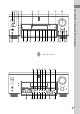
Table of Contents List of Button Locations and Reference Pages Main unit ............................................... 4 Getting Started 1: Check how to hookup your components ..................................... 6 1a: Connecting components with digital audio output jacks ............ 8 1b: Connecting components with multi channel output jacks .................. 11 1c: Connecting components with only analog audio jacks ..................... 13 2: Connecting the antennas ..................
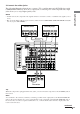
List of Button Locations and Reference Pages Illustration number How to use this page r Use this page to find the location of buttons and other parts of the system that are mentioned in the text.
6 7 8 9 0 + – wk wj wh wg wf wd ws wa v wl w; ql qk qj qh qg qf qd qsqa List of Button Locations and Reference Pages 1 23 4 5 Open the front door e; ea es ed ef eg + – – rf rd rs ra r; el ek + ej eh 5GB
Getting Started 1: Check how to hookup your components Steps 1a through 1c beginning on page 8 describe how to hook up your components to this receiver. Before you begin, refer to “Connectable components” below for the pages which describe how to connect each component. After hooking up all your components, proceed to “2: Connecting the antennas” (page 15).
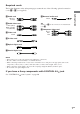
Required cords The hookup diagrams on the subsequent pages assume the use of the following optional connection cords (A to H) (not supplied). G Monaural audio cord White (L) Red (R) Black Tip B Audio/video cord Audio cord A can be torn into two monaural audio cords G.
1a: Connecting components with digital audio output jacks Hooking up a DVD player, LD player, TV, or satellite tuner For details on the required cords (A–H), see page 7. 1 Connect the audio jacks.
2 Connect the video jacks. The following illustration shows how to connect a TV or satellite tuner and a DVD/LD player with COMPONENT VIDEO (Y, B-Y, R-Y) output jacks. Connecting a TV with component video input jacks allows you to enjoy higher quality video. • On this receiver, the component video signals cannot be converted to S-video or standard video signals (or vice versa). • The on-screen display will not appear on a TV connected to the COMPONENT VIDEO MONITOR OUT jacks even if you press ON SCREEN.
1a: Connecting components with digital audio output jacks (continued) Hooking up a CD/Super Audio CD player and MD/DAT deck For details on the required cords (A–H), see page 7.
1b: Connecting components with multi channel output jacks If your DVD/LD and CD/Super Audio CD players are equipped with multi channel decoder, you can connect them to this receiver’s MULTI CHANNEL IN jacks to enjoy the sound of the connected component’s multi channel decoder. Alternatively, the multi channel input jacks can be used to connect an external multi channel decoder. For details on the required cords (A–H), see page 7. ANTENNA Getting Started 1 Connect the audio jacks.
1b: Connecting components with multi channel output jacks (continued) 2 Connect the video jacks. The following illustration shows how to connect a DVD or LD player with COMPONENT VIDEO (Y, B-Y, R-Y) output jacks. Connecting a TV with component video input jacks allows you to enjoy higher quality video. Notes • On this receiver, the component video signals cannot be converted to S-video or standard video signals (or vice versa).
1c: Connecting components with only analog audio jacks Getting Started Hooking up audio components For details on the required cords (A–H), see page 7.
1c: Connecting components with only analog audio jacks (continued) Hooking up video components If you connect your TV to the MONITOR jacks, you can watch the video from the selected input (function) (page 25). In addition, you can display the SURROUND, EQ, SET UP, CUSTOMIZE, LEVEL parameters and the selected sound field by pressing ON SCREEN. For details on the required cords (A–H), see page 7.
2: Connecting the antennas Connect the supplied AM loop antenna and FM wire antenna.
3: Connecting speakers Connect your speakers to the receiver. This receiver alows you to use a 7.1 channel speaker system. To fully enjoy theater-like multi channel surround sound requires five speakers (two front speakers, a center speaker, and two surround speakers) and a sub woofer (5.1 channel). You can enjoy high fidelity reproduction of DVD software recorded in the Surround EX format if you connect one additional surround back speaker (6.1 channel) or two additional surround back speakers (7.
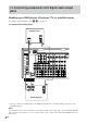
Required cords B Monaural audio cord (not supplied) A Speaker cords (not supplied) (+) Black Front speaker (R) Active sub woofer Front speaker (L) Center speaker INPUT AUDIO IN E B e E e A SPEAKERS FRONT B*1 e E A Getting Started (–) A AC OUTLET IMPEDANCE USE 4-16Ω VIDEO 2 VIDEO 1 S2 VIDEO OUT IN S2 VIDEO OUT IN SPEAKERS CTRL A1 R – + FRONT L – + – + CENTER – + A VIDEO OUT VIDEO IN OUT – + IN AUDIO OUT FRONT 8Ω AUDIO IN OUT IN SURROUND SURR BACK CENTE
4: Connecting the AC power cord Connect the supplied AC power cord to the AC IN terminal on the receiver, then connect the AC power cord to a wall outlet. You can connect up to one component to the AC OUTLET on the receiver.
Performing initial setup operations 1 Press ?/1 to turn off the receiver. 2 Hold down ?/1 for 5 seconds. “ENTER to Clear All” appears in the display for about 10 seconds. 3 While “ENTER to Clear All” appears in the display, press DOOR OPEN to open the door of the front panel, then press ENTER. After “MEMORY CLEARING...” appears in the display for a while, “MEMORY CLEARED!” appears. The following are reset to their factory settings. • All settings in the SET UP, CUSTOMIZE, SURROUND, LEVEL, and EQ menus.
5: Setting up the speakers (continued) x CENTER SP (Center speaker size) • LARGE If you connect a large speaker that will effectively reproduce bass frequencies, select “LARGE”. Normally, select “LARGE”. However, if the front speakers are set to “SMALL”, you cannot set the center speaker to “LARGE”.
x SURR BACK SP (Surround back speaker size) • LARGE If you connect a large speaker that will effectively reproduce bass frequencies, select “LARGE”. Normally, select “LARGE”. However, if the front speakers are set to “SMALL”, you cannot set the surround back speaker to “LARGE”.
5: Setting up the speakers (continued) sub woofer’s cut off frequency as high as possible. Initial setting: 5.0 meter x FRONT XX.X meter (Front speaker distance) Initial setting: 5.0 meter Lets you set the distance from your listening position to the front speakers (A). You can adjust from 1.0 meter to 12.0 meters in 0.1 meter steps. If both front speakers are not placed an equal distance from your listening position, set the distance to the closest speaker.
Give it a try! For advanced speaker setups The receiver lets you to input the speaker position in terms of distance. However, it is not possible to set the center speaker further than the front speakers. Also, the center speaker cannot be set more that 1.5 meters closer than the front speakers. Likewise, the surround speakers can not be set farther away from the listening position than the front speakers. And they can be no more than 4.5 meters closer.
6: Adjusting the speaker levels and balance (TEST TONE) Adjust the speaker levels and balance while listening the test tone from your listening position. Use the remote for the operation. Tips • The receiver employs a test tone with a frequency centered at 800 Hz. • Although these adjustments can also be made via the LEVEL button on the front panel, we recommend you follow the procedure described below and make adjustments from your listening position using the remote.
Amplifier/Tuner Operation Notes on using headphones Selecting the component 1 Rotate FUNCTION to select the function. The selected function appears in the display.
Listening to multi channel sound (MULTI CH DIRECT) You can select the audio directly from the components connected to the MULTI CHANNEL IN jacks. This function enables you to enjoy high quality analog sources like DVD or Super Audio CD. Also see “D.POWER” on page 47. Surround effects are not activated when using this function. Press MULTI CH DIRECT repeatedly to select the multi channel audio source (“MULTI CH 1 DIRECT” or “MULTI CH 2 DIRECT”). The selected audio source is output.
Direct tuning Enter a frequency of the station directly by using the NUM menu on the remote. For details on the supplied remote, refer to the operating instructions supplied with the remote. 1 Select “TUNER” from the FUNCTION You can also use the FUNCTION control on the receiver. 2 Press on the remote repeatedly until SUB menu appears, then select “FM/ AM” from the SUB menu to select the FM or AM band. You can also use the FM/AM button on the receiver. 3 Select “DIRECT TUNING” from the SUB menu.
Presetting radio stations You can preset up to 30 FM or AM stations. Then you can easily tune in the stations you often listen to. Presetting radio stations 1 Rotate FUNCTION to switch the Tuning to preset stations 1 Rotate FUNCTION to switch the function to TUNER. 2 Press PRESET TUNING + or – repeatedly to select the preset station you want. Each time you press the button, you can select the preset station as follows: nA1˜A2˜...˜A0˜B1˜B2˜...˜B0N function to TUNER.
Using the Radio Data System (RDS) (Models of area code CEL only) – Displaying RDS information – Scanning preset stations by program type Note that RDS is operable only for FM stations.* * Not all FM stations provide RDS service, nor do they provide the same types of services. If you are not familiar with the RDS services in your area, check with your local radio stations for details.
Using the Radio Data System (RDS) (continued) Program type indication Description of program types Leisure & Hobby Programs on recreational activities such as gardening, fishing, cooking, etc.
Changing the display Changing the information in the display Press DISPLAY repeatedly. The displayed information varies according to the selected function.
About the indications in the display 1 2 3 SW L C R L.F.E. SL S SR PRO LOGIC 4 6 COAX SLEEP MONO OPT STEREO DTS MPEG EQ qf qd qs qa q; 1 SW: Lights up when sub woofer selection is set to “YES” (page 21) and the receiver detects that the disc being played back does not contain the LFE channel signal. While this indicator lights up, the receiver creates a sub woofer signal based on the low frequency components of the front channels. 2 Playback channel indicators: The letters (L, C, R, etc.
0 MPEG: Lights up when MPEG signals are input. Note Only the front 2 channels are compatible with MPEG format. Multi channel surround sound is downmixed and output from the front 2 channels. qs OPT: Lights up when the source signal is a digital signal being input through the OPTICAL terminal. qd COAX: Lights up when the source signal is a digital signal being input through the COAXIAL terminal. qf L.F.E.: Lights up when the disc being played back contains the LFE (Low Frequency Effect) channel.
Enjoying Surround Sound Automatically decoding the input audio signal Using only the front speakers (2CH STEREO) (AUTO DECODING) In this mode, the receiver automatically detects the type of audio signal being input (Dolby Digital, DTS, standard 2 channel stereo, etc) and performs the proper decoding if necessary. This mode presents the sound as it was recorded/encoded, without adding any surround effects.
Selecting a sound field You can take advantage of surround sound simply by selecting one of the receiver’s pre-programmed sound fields. They bring the exciting and powerful sound of movie theaters and concert halls into your home. Sound field list CINEMA STUDIO EX A DCS CINEMA STUDIO EX B DCS CINEMA STUDIO EX C DCS MONO MOVIE STEREO MOVIE D.CONCERT HALL A D.CONCERT HALL B CHURCH OPERA HOUSE CINEMA STUDIO EX modes are suitable for watching motion picture DVDs (etc.), with multi channel surround effects.
Selecting a sound field (continued) Selecting the DIGITAL CONCERT HALL modes About CINEMA STUDIO EX modes These modes reproduce the acoustics of a concert hall by applying multi-speaker system dynamics to 2 channel audio signals, like those from CDs, etc. The CINEMA STUDIO EX modes consist of the following three elements. • Virtual Multi Dimension Creates 5 sets of virtual speakers from a single pair of actual surround speakers. Press MODE +/– repeatedly to select “D.CONCERT HALL A (or B)”.
Selecting other sound fields Press MODE +/– repeatedly to select the sound field you want. The selected sound field appears in the display. x NORMAL SURROUND x MONO MOVIE Creates a theater like environment from movies with monaural soundtracks. x STEREO MOVIE Creates a theater like environment from movies recorded with stereo soundtracks. x CHURCH Reproduces the acoustics of a stone church. x OPERA HOUSE Reproduces the acoustics of an opera house.
Selecting a sound field (continued) Enjoying the surround effect at low volume level (NIGHT MODE) This function allows you to retain a theater like environment at low volume levels. This function can be used with other sound fields. Enjoying Dolby Pro Logic II and DTS Neo:6 (2CH MODE) This function lets you specify the type of decoding for 2 channel audio sources. Press NIGHT MODE.
Tips • When “PLII MUSIC” is selected, you can make further adjustments using “CENTER WIDTH”, “DIMENSION”, “PANORAMA” in the SURROUND menu (page 53). • You can select the 2 channel decoding mode using “2CH MODE” in the CUSTOMIZE menu (page 47). Selecting the surround back decoding mode (SB DECODING) This function lets you select the decoding mode for the surround back signals of the multi channel input stream. * Dolby Digital EX, DTS-ES Matrix 6.1, DTS-ES Discrete 6.1, etc.
Selecting the surround back decoding mode (continued) How to select the surround back decoding mode You can select the surround back mode you want according to the input stream. When you select “AUTO” When the input stream contains the 6.1 channel decode flag*1, the appropriate decoder is applied to decode the surround back signal. For the DTS-ES Matrix 6.1 source, DTS Matrix decoder is applied. For the DTS-ES Discrete 6.1 source, DTS Discrete decoder is applied to reproduce the Discrete 6.
Advanced Adjustments and Settings Assigning the audio input Selectable audio inputs for each function DVD/LD, CD/SACD function (AUDIO SPLIT) NO ASSIGN t DIGITAL: ONLY COAX t DIGITAL: ONLY OPT t ONLY ANALOG INPUT You can assign the audio input for each function. This function is convenient in the following cases. TV/SAT, MD/DAT function (Example) When you have two DVD players and no digital audio input jack is available for the second DVD player.
Switching the audio input mode for digital components When the multi channel audio input is assigned to a specific function (page 47) (INPUT MODE) The following is displayed instead of “AUTO 2CH” and “ANALOG 2CH FIXED”. You can switch the audio input mode for functions which have digital audio input jacks. You can also select the COAXIAL or OPTICAL audio inputs of other functions using the AUDIO SPLIT (page 41).
Customizing sound fields By adjusting the SURROUND menu and LEVEL menu, you can customize the sound fields to suit your particular listening situation. Note on the displayed items The setup items you can adjust in each menu vary depending on the sound field. Certain setup parameters may be dimmed in the display. This means that the selected parameter is either unavailable or fixed and unchangeable. You can customize the surround effects of the selected sound field.
Customizing sound fields (continued) x CENTER XXX.X dB (Center speaker level) Adjusting the LEVEL menu x SURROUND L XXX.X dB (Surround speaker (L) level) You can adjust the balance and level of each speaker. These settings are applied to all sound fields. 1 Start playing a source encoded with multi channel surround effects (DVD, etc.). x SURR BACK XXX.X dB (Surround back speaker level)*1 x SURR BACK L XXX.X dB (Surround back speaker (L) level)*2 x SURR BACK R XXX.
For advanced LEVEL menu adjustments Adjusting the equalizer Use the CUSTOMIZE menu and set “MENU EXPAND” to “ON” to enable advanced adjustments. For details on “MENU EXPAND”, see page 47. For details on how to set the items, see page 54. Resetting sound fields to the initial settings ?/1. “S.F Initialize” appears in the display and all sound fields are reset to the initial settings.
Adjusting the equalizer (continued) EQ menu parameters To apply the stored equalizer Press EQ BANK repeatedly to select EQ [1]–[5]. Select “EQ [OFF]” to turn off equalization. x FRONT BASS XXX.X dB (Front speaker bass level) Clearing Stored Equalizer Settings x FRONT MID XXX.X dB (Front speaker midrange level) 1 Press EQ BANK repeatedly to select the equalizer (EQ [1]–[5]) you want to clear. x FRONT TREBLE XXX.X dB (Front speaker treble level) 2 Press EQ. x CENTER BASS XXX.
x 2CH MODE (2 channel decoding mode) Advanced settings Using the CUSTOMIZE menu to adjust the receiver You can adjust various receiver settings using the CUSTOMIZE menu. 1 Press CUSTOMIZE. The CUSTOMIZE button lights up and “<<>>” appears in the display. or ) to select the parameter. For details, see “CUSTOMIZE menu parameters” below. 3 Turn the jog dial to adjust the selected parameter. 4 Repeat steps 2 and 3 to adjust the other items.
Advanced settings (continued) x V.POWER (Video power management) • AUTO OFF Lets you turn off the power of the unnecessary video circuits automatically. You can enjoy high quality audio without the influence of video circuits. • ALWAYS ON Lets you keep the power of video circuits on. Depending on the monitor, noise may be produced or the picture may be distorted when the power of the video circuits is turned on. In this case, select “ALWAYS ON”. x S.
x COLOR SYSTEM (OSD color system) (Models of area code CEL only) Lets you select the color system. • NTSC • PAL x OSD COLOR (Color of the on-screen display) Lets you select the color of the on-screen display. • COLOR The on-screen display is displayed in color. • MONOCHROME The on-screen display is displayed in monochrome. Initial setting: 4 Lets you adjust the position of the on-screen display horizontally. You can adjust from 0 to 64. x OSD V.
Advanced settings (continued) x S.W PHASE (Sub woofer phase polarity) Lets you set the sub woofer phase polarity. • NORMAL Normally, select “NORMAL”. • REVERSE Depending on the type of front speakers, the position of the sub woofer, and the cut-off frequency of the sub woofer, setting the phase polarity to “REVERSE” (reverse) may produce better bass. Besides bass reproduction, the richness and tightness of the overall sound may also be affected.
Tip x SURR HEIGHT (Surround speaker height)*1 x SURR BACK HGT. (Surround back speaker height)*2 Lets you specify the height of your surround speakers and the surround back speakers for proper implementation of the surround effects of the Cinema Studio EX modes (page 35). B B 60 A A 30 • LOW Select if the height of your surround speakers or the surround back speakers corresponds to section A. • HIGH Select if the height of your surround speakers or the surround back speakers corresponds to section B.
Advanced settings (continued) Advanced SURROUND menu parameters x SURROUND SP > XXX Hz (Surround speaker crossover frequency) When “MENU EXPAND” is set to “ON”, all of the following parameters are displayed and adjustable. Initial setting: STD (120 Hz) Lets you adjust the surround speaker bass crossover frequency when “SURROUND SP” (surround speaker size) is set to “SMALL”. You can adjust from 40 Hz to 200 Hz in 10 Hz steps.
x C.WIDTH (Center width control) Initial setting: (3) Lets you perform further adjustments for Dolby Pro Logic II Music mode decoding (PLII MUSIC). You can set this parameter only when “2CH MODE” is set to “PLII MUSIC” (page 38) and NORMAL SURROUND is selected. You can adjust the distribution of the center channel signal, generated through the Dolby Pro Logic II decoding, to the L/R speakers.
Advanced settings (continued) Advanced LEVEL menu parameters x VIR.SPEAKERS (Virtual speakers) When “MENU EXPAND” is set to “ON”, all of the following parameters are displayed and adjustable. This parameter is especially for the Cinema Studio EX modes (page 35). • ON The virtual speakers are created. • OFF The virtual speakers are not created. x SURR ENHANCER (Surround reflection enhancer) This parameter is especially for the Cinema Studio EX modes (page 35).
x D.RANGE COMP. (Dynamic range compressor) Lets you compress the dynamic range of the sound track. This may be useful when you want to watch movies at low volumes late at night. • OFF The dynamic range is not compressed. • 0.1–0.9 The dynamic range is compressed in small steps to achieve the sound you desire. • STD The dynamic range is compressed as intended by the recording engineer. • MAX The dynamic range is compressed dramatically. “D.RANGE COMP.
Advanced settings (continued) x FRONT BASS XXX Hz (Front speaker bass frequency) Initial setting: 250 Hz You can adjust from 99 Hz to 1.0 kHz in 21 steps. x FRONT MID XXX Hz (Front speaker midrange frequency) Initial setting: 1.0 kHz You can adjust from 198 Hz to 10 kHz in 37 steps. x FRONT MID (Front speaker midrange bandwidth) • WIDE Provides a wide band centered on the selected frequency, for general adjustments. • MID Provides a normal band.
Other Operations 6 Press ENTER. Naming preset stations and functions You can enter a name of up to 8 characters for preset stations and functions and display it in the receiver’s display. 1 To index a preset station Rotate FUNCTION to select TUNER, then tune in the preset station you want to create an index name for (page 28). 2 Press CUSTOMIZE. The CUSTOMIZE button lights up and “<<>>” appears in the display. 3 Press the cursor button ( ) to select “NAME IN?”.
Using the Sleep Timer You can set the receiver to turn off automatically at a specified time by using the remote. For details, refer to the operating instructions supplied with the remote. Select SLEEP from the RECEIVER menu repeatedly while the power is on. Each time you select SLEEP, the display changes cyclically as follows: Selecting the speaker system Set the SPEAKERS switch according to the front speakers you want to drive.
Recording Before you begin, make sure you’ve connected all components properly. Recording on an audio tape or MiniDisc You can record on a MiniDisc or cassette tape using the receiver. See the operating instructions of your cassette deck or MD deck if you need help. Recording on a video tape You can record from a VCR, a TV, or an LD player using the receiver. You can also add audio from a variety of audio sources when editing a video tape.
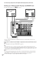
CONTROL A1 control system CONTROL A1 ANTENNA 75Ω COAXIAL FM DIGITAL COMPONENT VIDEO U AM CD/SACD OPTICAL IN MONITOR TV/SAT DVD/LD VIDEO 2 VIDEO 1 S2 VIDEO S2 VIDEO S2 VIDEO OUT IN IN S2 VIDEO OUT IN S2 VIDEO OUT IN TV/SAT IN DVD/LD IN MONITOR OUT CTRL A1 Y MD/DAT OPTICAL OUT PB/CB/B-Y MD/DAT OPTICAL IN PR/CR/R-Y VIDEO OUT PHONO CD/SACD TV/SAT OPTICAL IN IN IN MD/DAT OUT TAPE IN OUT IN VIDEO IN VIDEO IN OUT VIDEO AUDIO IN AUDIO IN OUT VIDEO IN OUT IN OUT AUDIO IN
CONTROL A1 compatibility and CONTROL A1 CONTROL A1 hookup • If you have a CONTROL A1 compatible Sony CD player, Super Audio CD player, tape deck, or MD deck Use a CONTROL A1 cord (mini jack) (not supplied) to connect the CONTROL A1 jack on the CD player, Super Audio CD player, tape deck, or MD deck to the CONTROL A1 jack on the receiver. See page 60 and the operating instructions supplied with your CD player, Super Audio CD player, tape deck, or MD deck for details.
CONTROL A1 (continued) control system Jacks and connection examples CONTROL A1 Basic Functions The CONTROL A1 functions will operate as long as the component you want to operate is turned on, even if all of the other connected components are not turned on.
x Synchronized recording This function lets you conduct synchronized recording between the selected source and recorder components. 1 Set the function selector on the amplifier (or receiver) to the source component. 2 Set the source component to pause mode (make sure both the N and X indicators light together). 3 Set the recorder component to the RECPAUSE mode. 4 Press PAUSE on the recorder component. Notes • Do not set more than one component to the pause mode.
Additional Information Precautions On safety Should any solid object or liquid fall into the cabinet, unplug the receiver and have it checked by qualified personnel before operating it any further. Troubleshooting If you experience any of the following difficulties while using the receiver, use this troubleshooting guide to help you remedy the problem. Should any problem persist, consult your nearest Sony dealer.
There is no sound or only a very low-level sound is heard. • Check that the speakers and components are connected securely. • Check that you have selected the correct component on the receiver. • Check that the SPEAKERS selector is not set to OFF (page 58). • Check that the headphones are not connected. • Press MUTING to cancel the muting function. • The protective device on the receiver has been activated because of a short circuit.
Troubleshooting (continued) Recording cannot be done. • Check that the components are connected correctly. • Select the source component with FUNCTION control. • When recording from a digital component, make sure the INPUT MODE is set to ANALOG 2CH FIXED (page 42) before recording with a component connected to the analog MD/DAT or TAPE terminals.
Specifications Amplifier section Models of area code TW POWER OUTPUT (8 ohms 20 Hz – 20 kHz, THD 0.05 %) 100 W + 100 W (4 ohms 20 Hz – 20 kHz, THD 0.09 %) 90 W + 90 W 1) Depending on the sound field settings and the source, there may be no sound output. Models of area code CEL, KR POWER OUTPUT (8 ohms 1 kHz, THD 0.7 %) 100 W + 100 W2) 90 W + 90 W3) (4 ohms 1 kHz, THD 0.7 %) 90 W + 90 W2) 80 W + 80 W3) Reference Power Output (8 ohms 1 kHz, THD 0.
Specifications (continued) EQ BASS: 99 Hz~1.0 kHz MID (FRONT L/R, CENTER only): 198 Hz~10 kHz TREBLE: 1.0 kHz~10 kHz Gain levels: ±10 dB, 0.5 dB step Video section Inputs/Outputs Video: S-video: COMPONENT VIDEO: 1 Vp-p, 75 ohms Y: 1 Vp-p, 75 ohms C: 0.286 Vp-p, 75 ohms Y: 1 Vp-p, 75 ohms B-Y: 0.7 Vp-p, 75 ohms R-Y: 0.7 Vp-p, 75 ohms General FM tuner section Power requirements Tuning range 87.5 - 108.
Index N Naming 57 A, B Adjusting brightness of the display 31 CUSTOMIZE parameters 47, 57 EQ parameters 45, 55 LEVEL parameters 44, 54 speaker volumes 24 SET UP parameters 19, 49 SURROUND parameters 43, 52 Automatic tuning 26 Changing display 31 effect level 43 Clearing receiver’s memory 19 Crossover frequency 51–52 CUSTOMIZE menu 47, 57 D Digital Cinema Sound 35 Direct tuning 27 Dubbing. See Recording E, F, G, H Editing. See Recording Effect level 43 EQ menu 45, 55 I, J, K Indexing.
GB
Additional Information 71GB
Sony Corporation 72GB Printed in Malaysia