
User's Manual


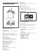


Table Of Contents

4
Parts Identification
a Antenna connector (BNC type)
Connect the supplied antenna here.
b Mounting screw
Use to attach the receiver to a camcorder or wireless
adapter.
c Accessory connector (15-pin D-sub)
Use to connect the receiver to a camcorder or wireless
adapter. Power, audio, and control signals are sent
through this connector.
d POWER indicator
Lights up green when the power is on.
The POWER1 and POWER2 indicators indicate the
power status of tuner 1 and tuner 2, respectively.
e RF (radio frequency) indicators
Indicate the RF input level of tuner 1 and tuner 2.
On in green: 25 dBµ or more
On in red: 15 dBµ to 25 dBµ
Off: Less than 15 dBµ
0 dBµ = 1 µV
EMF
f POWER switches
Turn tuner 1 and tuner 2 on or off individually.
g MENU button
Selects the displayed menu.
h SET button
Changes the item to be set or enters the selected function
or parameter value.
i + or – button
Use to select a function or value.
j Infrared transmission port
Transmits the frequency and compander mode settings
configured on the unit to the transmitter.
k Display section
A Audio input level meter
Indicates the input signal level.
B Peak indicator
Warns of excessive input by lighting up when the signal
is 3 dB below the level at which distortion begins.
C Group display
Displays the name of the receive group that is configured.
D Channel display
Displays the name of the receive channel that is
configured.
E RF level meter
Indicates the RF input level. The number of segments that
light up depends on the input level.
5 segments lit: 50 dBµ or higher
4 segments lit: 40 to 49 dBµ
3 segments lit: 30 to 39 dBµ
2 segments lit: 20 to 29 dBµ
1 segment lit: 10 to 19 dBµ
All segments off: 10 dBµ or less
Meter display