
users manual


13
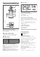
a Antenna
b PHONES (monitor) connector (3.5 mm
diameter, stereo mini jack)
Connect to headphones to monitor the audio output.
Do not connect headphones with a monaural mini jack.
This may short-circuit the headphone outputs, resulting in
distorted sound output.
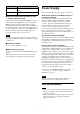
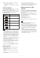
c POWER indicator
Displays the battery level.
d RF (radio frequency input) indicator
Displays the RF input level using the following colors.
On (green): Input level is 25 dBµ or more.
On (red): Input level is 15 dBµ to 25 dBµ.
Off: Input level is 15 dBµ or lower.
*0dBµ = 1µV
EMF
e + or – button
Selects functions or values shown on the display.
f N-Mark
Sends the set frequency and compander mode to the
transmitter. It also detects the tuner about the frequency
and compander mode set on the transmitter.
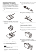
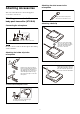
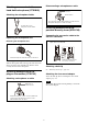
g Battery compartment
Accepts two AA batteries (alkaline, nickel metal hydride,
or lithium batteries).
For details on how to insert batteries, see “Power
Supply” (page 14).
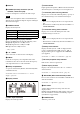
h Display section
A Audio input level meter
Displays the audio input level.
B Peak indicator
Lights up when the signal is 3 dB below the level at which
distortion begins as a warning of excessive input level.
C Transmitter power warning indicator
Displays an icon when the remaining battery capacity of
the transmitter being received is almost discharged.
• The icon is not displayed if the receive signal level is
low.
• This function is enabled only when the transmitter is a
UTX-B40/M40/P40.
D Transmitter muting status indicator
Displays an icon when the muting function of the
transmitter being received is on.
• The icon is not displayed if the receive signal level is
low.
• This function is enabled only when the transmitter is a
UTX-B40/M40/P40.
E Battery level indicator
Displays the battery level. “USB” is displayed when
power is supplied from the USB connector. “MI” is
displayed when power is supplied from an SMAD-P5
(not supplied).
For details, see “Battery level indicator” (page 16).
F RF level (reception level) indicator
Indicates the current reception level.
G Menu display section
Displays various functions. Press the + or – button to
switch functions.
For details, see “Configuration menu” (page 23).
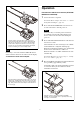
i NFC SYNC (NFC communication) button
Press to start a channel scan and for NFC communication
with the transmitter.
For details, see “Operation” (page 19).
j SET button
Adjusts displayed function settings and enters the
displayed value.
Holding down the SET button while turning on the power
turns the transmitter on without transmitting a signal
(transmission stopped mode).
k POWER button
Turns the power on/off.
Note
Indicator display Status
On (green) Sufficient battery level
Flashing (green) Battery is getting low
Off Supply OFF
Notes
Notes