DC POWER SUPPLY UNIT DC-78 SERVICE MANUAL 1st Edition
! WARNING This manual is intended for qualified service personnel only. To reduce the risk of electric shock, fire or injury, do not perform any servicing other than that contained in the operating instructions unless you are qualified to do so. Refer all servicing to qualified service personnel. ! WARNUNG Die Anleitung ist nur für qualifiziertes Fachpersonal bestimmt. Alle Wartungsarbeiten dürfen nur von qualifiziertem Fachpersonal ausgeführt werden.
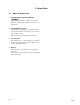
1. Service Overview 1-1. Removal the Input Connector 3 Remove the case lid. 1-2. Removal the Transformer Mounted Circuit Board 1 Connector screw 6 P 2x7 LW2 2 Press both claws. 4 Battery sleeve 2 Cannon pin insert (3-pin) VIO Battery case 5 K 2x3 Cannon pin sleeve BLK GRN 3 Remove the three leads. 1 Battery sleeve 2 Spring Battery case Cannon pin sleeve 4 Nut and Washer Transformer mounted circuit board Cap Battery case VIO ORG RED Screwdriver (2 mm dia.
2. Board Layout TRANSFORMER MOUNTED CIRCUIT BOARD GRN 5 T RED 2 2 BLK 0 YEL 4 CN (S) 4P SOLDER SIDE 1 4 VIO 7 BATTERY 1.5 V 1 3 CN PIN INSERT (XLR-3-14) SOLDER SIDE SOLDER SIDE ORG 3 WHT 9 2 3 ORG 3 VIO 7 3. Schematic Diagram 1S133T 22 k BATTERY 1.5 V 68µ/6.
4. Spare Parts 4-1. Notes on Repair Parts 1. Safety Related Components Warning w Components marked ! are critical to safe operation. Therefore, specified parts should be used in the case of replacement. 2. Standardization of Parts Some repair parts supplied by Sony differ from those used for the unit. These are because of parts commonality and improvement. Parts list has the present standardized repair parts. 3.
4-2. Exploded Views and Parts List K 2x3 8 A 5 1 K 2x3 4 6 K 2x3 LW2 P 2x7 12 K 2x3 7 K 2x3 9 10 2 3 A 11 13 No. Part No.
Printed in Japan DC-78 (SYM) J, E 9-976-910-01 Sony Corporation 2002.