4-090-076-42 (1) Data Projector Data Projector VPL-CS5/VPL-CX5 Operating Instructions GB Mode d’emploi FR Manual de instrucciones ES VPL-CS5 VPL-CX5 © 2002 Sony Corporation
WARNING To prevent fire or shock hazard, do not expose the unit to rain or moisture. To avoid electrical shock, do not open the cabinet. Refer servicing to qualified personnel only. The number below is for FCC related matters only. Declaration of Conformity Trade Name: SONY Model No.: VPL-CS5/VPL-CX5 Responsible Party: Sony Electronics Inc. Address: 680 Kinderkamack Road, Oradell, NJ 07649 U.S.A. Telephone No.: 201-930-6972 This device complies with Part 15 of the FCC Rules.
For the customers in Canada This Class B digital apparatus complies with Canadian ICES-003. Voor de klanten in Nederland Gooi de batterij niet weg maar lever deze in als klein chemisch afval (KCA). The socket-outlet should be installed near the equipment and be easily accessible.
GB 4
Table of Contents Overview The INSTALL SETTING Menu ..... 34 The INFORMATION Menu ............ 35 Precautions .........................................6 Notes on Installation .......................... 7 Unsuitable Installation .................. 7 Unsuitable Conditions .................. 7 Features .............................................. 8 Location and Function of Controls .10 Top/Front/Left Side ....................10 Rear/Right Side/Bottom .............10 Control Panel ..........................
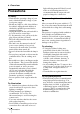
B Overview Precautions light-reflecting material. If the floor and walls are of reflecting material, it is recommended that the carpet and wall paper be changed to a dark color. On safety • Check that the operating voltage of your unit is identical with the voltage of your local power supply. • Should any liquid or solid object fall into the cabinet, unplug the unit and have it checked by qualified personnel before operating it further.
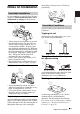
Notes on Installation internal heat of the projector. Clean it up periodically. Unsuitable Installation Overview Do not install the projector in the following situations. These installations may cause malfunction or damage to the projector. Poorly ventilated Unsuitable Conditions Do not use the projector under the following conditions. Toppling the unit Avoid using as the unit topples over on its side. It may cause malfunction. • Allow adequate air circulation to prevent internal heat build-up.
Note Easy presentation Installing the unit at altitudes Before installing the unit at altitudes higher than 1500 m (4921 feet), consult qualified Sony personel. Installation at such altitudes may affect the reliability of the projector. Features High operability • Intelligent Auto-setup function Simply press the power key, and the projector automatically performs the setups required before use. The projector opens the lens protector, corrects the V Keystone, and sets optimum conditions for projection.
Overview • High resolution For VPL-CX5: Three superhigh-aperture 0.7-inch XGA panels with approximately 790,000 pixels, and with micro-lens array, provide a resolution of 1024 × 768 dots (horizontal/vertical) for RGB input, and 750 horizontal TV lines for video input. For VPL-CS5: Three superhigh-aperture 0.7-inch SVGA panels with approximately 480,000 pixels provide a resolution of 800 × 600 dots (horizontal/ vertical) for RGB input, and 600 horizontal TV lines for video input.
Location and Function of Controls 1 I / 1 (on/standby) key Turns on and off the projector when the projector is in standby mode. The ON/ STANDBY indicator around the I / 1 key lights in green when the power is turned on. When turning off the power, press the I / 1 key twice following the message on the screen, or press and hold the key for about two seconds. Top/Front/Left Side 1 2 3 4 For details on steps for turning off the power, see “To turn off the power” on page 26.
5 Lens protector (lens cover) The lens protector automatically opens when the power is turned on. 6 Front remote control detector To adjust the height Adjust the height of the projector as follows: 1 Overview 7 Ventilation holes (exhaust) How to use the powered tilt adjuster Press the I / 1 key The lens protector opens, and the powered tilt adjuster rises automatically. The adjuster stops at its previously adjusted position.
5 TEMP (Temperature)/FAN indicator Control Panel Lights up or flashes under the following conditions: – Lights up when temperature inside the projector becomes unusually high. – Fashes when the fan is broken. POWER SAVING INPUT A ACCESS MENU PUSH ENTER For details, see page 41.
control the mouse function with the supplied Remote Commander. The supplied application software (VPLCX5 only) can be installed in the computer attached to this connector. The Memory Stick can be inserted. Never insert an object other than the Memory Stick. For details, see the attached “Operating Instructions” for Memory Stick. The keys that have the same names as those on the control panel function identically.
• You can cancel the adjustment by pressing the APA key again while “Adjusting” appears on the screen. • The picture may not be adjusted properly depending on the kinds of input signals. • Adjust the items “Dot Phase,” “H Size” and “Shift” in the INPUT SETTING menu when you adjust the picture manually. 3 PIC MUTING key Used to mute the picture temporarily. Press again to restore the picture. 4 ENTER key 5 Keys emulate a mouse Functions like a mouse of a computer connected via USB with the projector.
To install batteries 1 Push and slide to open the lid, then install the two size AA (R6) batteries (supplied) with the correct polarity. Overview While pressing the lid, slide it. Be sure to install the battery from the # side. 2 Replace the lid. Notes on batteries • Make sure that the battery orientation is correct when inserting batteries. • Do not mix an old battery with a new one or different types of batteries.
B Setting Up and Projecting Installing the Projector This section describes how to install the projector. The distance between the lens and the screen varies depending on the size of the screen. Use the following table as a guide. Distance between the screen and the center of the lens Unit: m (feet) Screen size (inches) 40 60 80 100 120 150 Minimum Distance 1.5 (4.9) 2.3 (7.5) 3.1 (10.2) 3.9 (12.8) 4.7 (15.4) 5.9 (19.4) Maximum Distance 1.9 (6.2) 2.9 (9.5) 3.8 (12.5) 4.8 (15.7) 5.
Connecting the Projector When you connect the projector, make sure to: • Turn off all equipment before making any connections. • Use the proper cables for each connection. • Insert the cable plugs firmly; loose connections may increase noise and reduce performance of picture signals. When pulling out a cable, be sure to pull it out from the plug, not the cable itself Setting Up and Projecting To connect the projector, refer to the illustrations on the next and the following pages.
To connect an IBM PC/AT compatible computer Left side Computer POWER SAVING INPUT A ACCESS MENU to monitor output PUSH ENTER AUDIO VIDEO S VIDEO TEMP/FAN LAMP/COVER HD D-sub 15-pin cable (supplied) Stereo audio connecting cable (not supplied)a) to audio output USB cable (supplied) (Connect the USB cable to use a wireless mouse or the Projector Station.) to USB connector a) Use a no-resistance cable.
Connecting with a VCR or 15k RGB/Component Equipment This section describes how to connect the projector to a VCR and 15k RGB/ component equipment. For more information, refer to the instruction manuals of the equipment you are connecting.
To connect a 15k RGB/Component equipment SMF-402 Signal Cable (not supplied) HD D-sub 15-pin (male) ↔ 3 × phono jack Left side POWER SAVING INPUT A ACCESS MENU PUSH ENTER AUDIO VIDEO S VIDEO TEMP/FAN Stereo audio connecting cable (not supplied)a) LAMP/COVER to audio output a) Use a no-resistance cable. to RGB/ component output 15k RGB/Component equipment Notes • Set the aspect ratio using “Wide Mode” in the INPUT SETTING menu according to the input signal.
Selecting the Menu Language You can select one of nine languages for displaying the menu and other onscreen displays. The factory setting is English. To change the menu language, proceed as follows: Setting Up and Projecting Front remote control detector POWER SAVING FREEZE MS SLIDE I / 1 INPUT A KEYSTONE INPUT MENU MENU APA PIC ENTER ACCESS MUTING PUSH ENTER AUDIO VIDEO S VIDEO TEMP/FAN LAMP/COVER 1 Open the connector panel, then plug the AC power cord into a wall outlet.
4 Press the M or m key to select the MENU SETTING menu, then press the , or ENTER key. The selected menu appears. Input A : : A : : 5 Press the M or m key to select “Language,” then press the , or ENTER key. Input A 6 Press the M or m key to select a language, then press the < or ENTER key. The menu changes to the selected language. To clear the menu Press the MENU key. The menu disappears automatically if a key is not pressed for one minute.
Projecting Setting Up and Projecting Rear remote control detector 7 6 FREEZE MS SLIDE I / 1 KEYSTONE INPUT MENU APA PIC TILT ENTER MUTING 2 ON/STANDBY indicators 4 1 Open the connector panel, plug the AC power cord into a wall outlet, then connect all equipment. The ON/STANDBY indicator lights in red and the projector goes into standby mode. 2 Press the I / 1 key. The ON/STANDBY indicator lights in green and the Intelligent Auto-setup starts.
F7 or Fx Fn 4 Press the INPUT key to select the input source. To input from Press INPUT to display Computer connected to the INPUT A connector INPUT A Memory Stick inserted to the Memory Stick slot MS Video equipment connected to the VIDEO input connector VIDEO Video equipment connected to the S VIDEO input connector S VIDEO Smart APA (Auto Pixel Alignment) adjusts the picture of the connected equipment so that it is projected clearly.
Note The auto keystone adjustment may not correct the trapezoidal distortion perfectly, depending on the room temperature or the screen angle. In this case, adjust it manually. Press the KEYSTONE key on the Remote Commander until “V Keystone” appears on the screen, and adjust the value with the M/m/
To turn off the power 1 Press the I / 1 key. “POWER OFF? Please press I / 1 key again.” appears to confirm that you want to turn off the power. Note A message disappears if you press any key except the I / 1 key, or if you do not press any key for five seconds. 2 Press the I / 1 key again. The powered tilt adjuster is put away in the projector and the lens protector closes. The ON/STANDBY indicator flashes in green and the fan continues to run for about 90 seconds to reduce the internal heat.
Effective Tools for Your Presentation To enlarge the image (Digital Zoom function) You can select a point in the image to enlarge. This function works when a signal from a computer is input, or when a still picture (except a movie picture) stored in a Memory Stick is projected (VPL-CX5 only). This function does not work when a video signal is input. 1 Press the D ZOOM + key on the Remote Commander. The digital zoom icon appears in the center of the image.
B Adjustments and Settings Using the Menu Using the MENU 1 The menu appears. The menu presently selected is shown as a yellow button. The projector is equipped with an on-screen menu for making various adjustments and settings. The setting items are displayed in a pop-up menu or in a sub menu. If you select an item name followed by dots (...), a sub menu with setting items appear. You can change the tone of the menu display and the menu language displayed in the on-screen menu.
4 Make the setting or adjustment on an item. • When changing the adjustment level: To increase the number, press the M or , key. To decrease the number, press the m or < key. Press the ENTER key to restore the previous screen. • When changing the setting: Press the M or m key to change the setting. Press the ENTER or < key to restore the previous screen. The PICTURE SETTING Menu The PICTURE SETTING menu is used for adjusting the picture or volume.
Adjust Picture... Menu Items The unit can store the setting values of the following sub menu items for each “Dynamic” or “Standard” picture mode separately. Contrast Adjusts the picture contrast. The higher the setting, the greater the contrast between a dark portion and a bright portion of the picture. The lower the setting, the lower the contrast. Brightness Adjusts the picture brightness. The higher the setting, the brighter the picture. The lower the setting, the darker the picture.
The INPUT SETTING Menu The INPUT SETTING menu is used to adjust the input signal. Items that cannot be adjusted depending on the input signal are not displayed in the menu. For details on the unadjustable items, see page 45. When the video signal is input INPUT SETTING Wide Mode: Video Off H Size Adjusts the horizontal size of picture output from a connector. The higher the setting, the larger the horizontal size of the picture. The lower the setting, the smaller the horizontal size of the picture.
About the Preset Memory No. This projector has 38 types of preset data for input signals (the preset memory). When a preset signal is input, the projector automatically detects the signal type and recalls the data for the signal from the preset memory to adjust it to an optimum picture. The memory number and signal type of that signal are displayed in the INFORMATION menu (See page 35). You can also adjust the preset data through the INPUT SETTING menu.
indicates the input channel when the power is turned on or the INPUT key is pressed. Input-A Signal Sel. The MENU SETTING Menu Selects the computer, component or video GBR signal input from the INPUT A connector. The MENU SETTING menu is used for changing the settings of the projector. Note If the setting is not correct, the color of the picture becomes strange or “Please check INPUT-A setting.” appears on the screen and the picture is not displayed.
The INSTALL SETTING Menu The INSTALL SETTING menu is used for changing the settings of the projector. INSTALL SETTING Tilt... V Key s t o n e : I m ag e F l i p : B a ck g ro u n d : Lamp Mode: Input A Image Flip Flips the image on the screen horizontally and/or vertically. Off: The image does not flip. HV: Flips the image horizontally and vertically. H: Flips the image horizontally. V: Flips the image vertically.
The INFORMATION Menu The INFORMATION menu displays the horizontal and vertical frequencies of the input signal and the used time of the lamp. I N F O R M AT I O N Input A fH: fV: 48.47kHz 60.00Hz No.23 1024x768 Lamp Timer: 0H Memory number of a input signal Signal type Adjustments and Settings Using the Menu Menu Items fH Displays the horizontal frequency of the input signal. The displayed value is approximate. fV Displays the vertical frequency of the input signal.
B Maintenance Maintenance 2 Open the lamp cover by loosening a screw with the Phillips screwdriver (supplied with the Projector Lamp). Replacing the Lamp Replace the lamp with a new one in the following case. • When the lamp has burnt out or dims • “Please replace the LAMP.” appears on the screen • The LAMP/COVER indicator lights up The lamp life varies depending on conditions of use. Use LMP-C150 Projector Lamp as the replacement lamp.
4 Insert the new lamp all the way in until it is securely in place. Tighten the screws. Fold the handle. Cleaning the Air Filter The air filter should be cleaned every 300 hours. Remove dust from the outside of the ventilation holes with a vacuum cleaner. When it becomes difficult to remove the dust from the filter with a vacuum cleaner, remove the air filter and wash it. Notes 5 Close the lamp cover and tighten the screws. 6 Turn the projector back over.
4 Remove the air filter. 5 Wash the air filter with a mild detergent solution and dry it in a shaded place. 6 Attach the air filter and replace the cover. Notes • If you neglect to clean the air filter, dust may accumulate, clogging it. As a result, the temperature may rise inside the unit, leading to a possible malfunction or fire. • If the dust cannot be removed from the air filter, replace the air filter with the supplied new one.
Troubleshooting If the projector appears to be operating erratically, try to diagnose and correct the problem using the following instructions. If the problem persists, consult with qualified Sony personnel. Power Symptom Cause and Remedy The power is not turned on. • The power has been turned off and on with the I / 1 key at a short interval. c Wait for about 90 seconds before turning on the power (see page 26). • The lamp cover is detached. c Close the lamp cover securely (see page 36).
Symptom Cause and Remedy “Please check INPUT-A • Setting of “Input-A Signal Sel.” in the SET SETTING menu is setting.” appears in spite of incorrect. inputting the correct signal c Select “Computer,” “Video GBR” or “Component” correctly from INPUT A. according to the input signal (see page 33). On-screen display does not • “Status” in the SET SETTING menu has been set to “Off.” appear. c Set “Status” in the SET SETTING menu to “On” (see page 32). Color balance is incorrect.
Remote Commander Symptom Cause and Remedy The Remote Commander does not work. • The Remote Commander batteries are dead. c Replace with a new battery (see page 15). Others Symptom Cause and Remedy The LAMP/COVER indicator flashes. • The lamp cover or the air filter cover is detached. c Attach the cover securely (see pages 36 and 37). The LAMP/COVER indicator lights up. • The lamp has reached the end of its life. c Replace the lamp (see page 36). • The lamp becomes a high temperature.
Caution Messages Use the list below to check the meaning of the messages displayed on the screen. GB Message Meaning and Remedy Not applicable! • You have pressed the wrong key. c Press the appropriate key.
B Other Specifications Optical characteristics There may be a slight difference between the actual value and the design value shown above. 1) ANSI lumen is a measuring method of American National Standard IT 7.228. Electrical characteristics Color system NTSC3.58/PAL/SECAM/ NTSC4.
VD: Vertical sync input: 1-5 Vp-p high impedance, positive/ negative AUDIO Stereo minijack 500 mVrms, impedance more than 47 kilohms USB Up (female) × 1 Memory Stick Slot × 1 (VPL-CX5 only) Safety regulations UL60950, cUL (CSA No. 60950), FCC Class B, IC Class B, NEMKO (EN60950), CE (LVD, EMC), C-Tick General 285 × 68 × 228 mm (11 /4 × 2 5/8 × 9 inches) (w/h/d) (without the projection parts) Mass Approx. 2.7 kg (5 lb 15 oz) Power requirements AC 100 to 240 V, 50/60 Hz Power consumption Max.
Input signals and adjustable/ setting items Adjust Picture... menu Item Input signal Video or S video (Y/C) Com- Video Component GBR puter B&W Contrast z z z z Brightness z z z z z Color z z z – – z – – – – Hue z (NTSC 3.58/ 4.43 only) Sharpness z z z – z RGB Enhancer – – – z – Gamma Mode – – z z – Color Temp.
Preset signals Memory Preset signal No. fH (kHz) fV (Hz) 1 Video 60 Hz 15.734 59.940 2 Video 50 Hz 15.625 50.000 3 15k RGB/Component 60 Hz 15.734 59.940 S on G/Y or Composite Sync 4 15k RGB/Component 50 Hz 15.625 50.000 S on G/Y or Composite Sync 6 640 × 350 VGA mode 1 31.469 70.086 H-pos, V-neg 800 VGA VESA 85 Hz 37.861 85.080 H-pos, V-neg 832 PC-9801 Normal 24.823 56.416 H-neg, V-neg 848 VGA mode 2 31.469 70.
Memory Preset signal No. 34* 1280 × 1024 fH (kHz) fV (Hz) SXGA VESA 43 Hz 46.433 86.872 Sync SIZE H-pos, V-pos 1696 35 SGI-5 53.316 50.062 S on G 1680 36 SXGA VESA 60 Hz 63.974 60.013 H-pos, V-pos 1696 37 SXGA VESA 75 Hz 79.976 75.025 H-pos, V-pos 1688 38 SXGA VESA 85 Hz 91.146 85.024 H-pos, V-pos 1296 SXGA+ 60 Hz 60.020 H-pos, V-pos 1685 52 1400 × 1050 63.981 Memory No. 1 to No. 26 (VPL-CS5) Memory No. 1 to No. 38, No.
notes ............................. 7 unsuitable conditions .... 7 unsuitable installation .. 7 Index A L Adjusting memory of the settings 29 the picture ...................29 the picture size/shift ...31 Air filter .........................37 Auto Input Search ..........32 Lamp Mode .................... 34 Lamp replacement .......... 36 Lamp Timer ................... 35 Language ........................ 33 selecting the menu language .............. 21 Location and function of controls connector panel .
Other Index 49 GB
AVERTISSEMENT Afin d’éviter tout risque d’incendie ou d’électrocution, n’exposez pas cet appareil à la pluie ou à l’humidité. Afin d’éviter tout risque d’électrocution, n’ouvrez pas le châssis. Confiez l’entretien uniquement à un personnel qualifié. Pour les utilisateurs au Canada Cet appareil numérique de la classe B est conforme à la norme NMB-003 du Canada. La prise doit être près de l’appareil et facile d’accès.
Table des matières Généralités Précautions .........................................4 Réglages et paramétrages à l’aide du menu Remarques sur l’installation ............... 5 Utilisation du menu ......................... 29 Installation déconseillée ............... 5 Positions déconseillées ................. 6 Caractéristiques .................................. 7 Menu PARAMÉTRAGE DE L’IMAGE ....................................... 30 Emplacement et fonction des commandes ...............................
B Généralités Précautions Sécurité • Assurez-vous que la tension de service de votre appareil est identique à la tension secteur locale. • Si du liquide ou un objet quelconque venait à pénétrer dans le châssis, débranchez l’appareil et faites-le vérifier par un technicien qualifié avant de continuer à l’utiliser. • Débranchez l’appareil de la prise murale si vous n’avez pas l’intention de l'utiliser pendant plusieurs jours. • Pour débrancher le cordon, tirez-le par la fiche.
Nettoyage Remarques sur l’installation Installation déconseillée N’installez pas le projecteur dans les conditions suivantes. Ces installations peuvent entraîner un dysfonctionnement ou causer des dommages au projecteur. Mauvaise ventilation Projecteur LCD • Le projecteur LCD est fabriqué selon une technologie de fabrication de haute précision. Il est cependant possible que de petits points noirs ou lumineux (rouges, bleus ou verts) apparaissent sur le projecteur LCD.
Exposition à la chaleur et à l’humidité Positions déconseillées N’utilisez pas le projecteur dans les conditions suivantes. N’installez pas le projecteur sur son flanc. • N’installez pas l’appareil dans un endroit très chaud, très humide ou très froid. • Pour éviter la condensation d’humidité, n’installez pas l’appareil dans un endroit où la température peut augmenter rapidement. Évitez d’utiliser le projecteur dans une position qui pourrait entraîner un basculement.
Remarque peuvent être sélectionnés automatiquement ou manuellement. Installation de l’appareil en altitude Caractéristiques Facilité d’utilisation • Fonction d’autoréglage intelligent Appuyez simplement sur la touche d’alimentation. Le projecteur effectue automatiquement les réglages nécessaires avant l’utilisation. Il ouvre le protecteur d'objectif, corrige la distorsion trapézoïdale verticale et définit les meilleures conditions pour la projection. Cette fonction est appelée “autoréglage intelligent”.
Luminosité élevée, haute qualité d’image • Luminosité élevée L’adoption du nouveau système optique à haute performance de Sony confère à la lampe UHP 165 W un rendement lumineux de 1 800 ANSI lumen (VPLCX5) ou 1 600 ANSI lumen (VPL-CS5).
Pour plus d’informations sur la mise hors tension, voir “Pour mettre le projecteur hors tension” à la page 26. Emplacement et fonction des commandes 2 Indicateur ON/STANDBY (autour de la touche I / 1 ) Face supérieure/avant/ gauche 1 2 3 4 TILT 5 7 6 8 Pour plus d’informations sur les indicateurs LAMP/COVER et TEMP/ FAN, voir page 42.
8 Panneau de connecteurs/ Panneau de commande Pour plus d’informations, voir “Panneau de connecteurs” à la page 12 et “Panneau de commande” à la page 11. 9 Capteur de télécommande arrière Comment utiliser le dispositif de réglage d’inclinaison motorisé Pour régler la hauteur Pour régler la hauteur du projecteur, procédez comme suit : 1 Appuyez sur la touche I / 1. Le protecteur d’objectif s’ouvre et le dispositif de réglage d’inclinaison motorisé remonte automatiquement.
2 Touche MENU Remarques Permet d’afficher l’écran de menu. Appuyez à nouveau sur cette touche pour faire disparaître le menu. 3 Touches fléchées (f/F/g/G) Permettent de sélectionner le menu ou d’effectuer divers réglages. Généralités • Veillez à ne pas abaisser le projecteur sur vous doigts. • N'exercez pas une trop forte pression sur le dessus du projecteur lorsque le dispositif de réglage d’inclinaison est déployé. Ceci pourrait provoquer un dysfonctionnement.
4 Connecteur AUDIO (miniprise stéréo) Panneau de connecteurs 1 2 POWER SAVING 3 INPUT A MENU 4 5 6 7 ACCESS PUSH ENTER AUDIO VIDEO S VIDEO TEMP/FAN LAMP/COVER 1 Connecteur INPUT A (HD D-sub à 15 broches, femelle) Permet de raccorder un appareil externe tel qu’un ordinateur. Raccordez-le à la sortie moniteur d’un ordinateur à l’aide du câble fourni. Pour une entréé de signal composantes ou RVB 15 k, utilisez un câble en option.
Remarques Télécommande Les touches portant le même nom que celles du panneau de commande ont la même fonction. qf qd FREEZE MS SLIDE I / 1 qs KEYSTONE INPUT APA qa MENU 0 PIC 1 2 3 ENTER 4 MUTING 5a Généralités qg • Appuyez sur la touche APA alors qu’une image plein écran est affichée. S’il y a des bords noirs autour de l’image, la fonction APA ne fonctionnera pas correctement et il se peut que l’image dépasse de l’écran.
sur la touche FUNCTION. Ceci augmente l’impact de votre présentation. Pour utiliser cette fonction, affectez un fichier à la touche FUNCTION à l’aide du logiciel d’application fourni. réglage, utilisez les touches fléchées (M/ m/
nettoyez et séchez le logement des piles, puis remplacez les piles par des neuves. Généralités Remarques sur le fonctionnement de la télécommande • Assurez-vous qu’il n’y a aucun obstacle au faisceau infrarouge entre la télécommande et le capteur de télécommande sur le projecteur. Pointez la télécommande vers le capteur de télécommande avant ou arrière. • La portée de la télécommande est limitée.
B Installation et projection Installation du projecteur Cette section décrit comment installer le projecteur. La distance entre l’objectif et l’écran varie suivant la taille de l’écran. Utilisez le tableau suivant comme guide. Distance entre l’écran et le centre de l’objectif.
Raccordement du projecteur Lors du raccordement du projecteur : • Mettez tous les appareils hors tension avant tout raccordement. • Utilisez les câbles appropriés pour chaque raccordement. • Branchez correctement les fiches des câbles. Les mauvais contacts peuvent augmenter le bruit et réduire les performances des signaux d’image. Débranchez les câbles en les tenant par leur fiche. Ne tirez pas sur le câble lui-même.
Raccordement à un ordinateur compatible IBM PC/AT Côté gauche Ordinateur POWER SAVING INPUT A ACCESS MENU vers sortie moniteur PUSH ENTER AUDIO VIDEO S VIDEO TEMP/FAN LAMP/COVER Câble HD D-sub à 15 broches (fourni)* Câble de raccordement audio stéréo (non fourni)a) vers sortie audio Câble USB (fourni) (Pour utiliser une souris sans fil ou le logiciel Projector Station, raccordez le câble USB.) vers le connecteur USB a) Utilisez un câble sans résistance.
Raccordement à un magnétoscope ou un appareil à sortie RVB 15 k / composantes Cette section décrit comment raccorder le projecteur à un magnétoscope et à un appareil à sortie RVB 15 k/composantes. Pour plus d’informations, consultez le mode d’emploi de l’appareil à raccorder.
Pour raccorder un appareil à sortie RVB 15 k/composantes Côté gauche Câble de signal SMF-402 (non fourni) HD D-sub 15 à broches (mâle) ↔ 3 × prise Cinch POWER SAVING INPUT A ACCESS MENU PUSH ENTER AUDIO VIDEO S VIDEO TEMP/FAN Câble de raccordement audio stéréo (non fourni)a) LAMP/COVER vers sortie audio a) Utilisez un câble sans résistance.
Sélection de la langue de menu Vous pouvez sélectionner l’une des neuf langues de menu et d’affichage sur écran. La langue par défaut est l’anglais.
4 Appuyez sur la touche M ou m pour sélectionner le menu RÉGLAGE DE MENU, puis, appuyez sur la touche , ou ENTER. Le menu sélectionné apparaît. Input A : : A : : 5 Appuyez sur la touche M ou m pour sélectionner “Langage”, puis appuyez sur la touche , ou ENTER. Input A 6 Appuyez sur la touche M ou m pour sélectionner une langue, puis appuyez sur la touche < ou ENTER. La langue de menu est remplacée par celle que vous avez sélectionnée. Pour faire disparaître le menu Appuyez sur la touche MENU.
Projection Installation et projection Capteur de télécommande arrière 7 6 FREEZE MS SLIDE I / 1 KEYSTONE INPUT MENU APA PIC TILT ENTER MUTING Indicateur ON/STANDBY 2 4 1 Ouvrez le panneau de connecteurs, branchez le cordon d’alimentation secteur à une prise murale, puis raccordez tout l’équipement. L’indicateur ON/STANDBY s’allume en rouge et le projecteur est mis en veille. 2 Appuyez sur la touche I / 1. L’indicateur ON/STANDBY s’allume en vert et l’autoréglage intelligent commence.
F7 ou Fx Fn 4 Appuyez sur la touche INPUT pour sélectionner la source d’entrée.
Remarque Selon la température ambiante ou l’angle de l’écran, il se peut que le réglage automatique de la distorsion trapézoïdale ne corrige pas parfaitement la distorsion trapézoïdale. Réglez-la alors manuellement. Appuyez sur la touche KEYSTONE de la télécommande jusqu’à ce que “Trapèze V” apparaisse à l’écran, puis réglez la valeur avec la touche M/m/
Pour mettre le projecteur hors tension 1 Appuyez sur la touche I / 1. “METTRE HORS TENSION? Appuyez a nouveau sur la touche I / 1”. apparaît pour vous permettre de confirmer votre intention de mettre le projecteur hors tension. Remarque Le message disparaît si vous appuyez sur une touche autre que I / 1 ou si vous n’appuyez sur aucune touche pendant cinq secondes. 2 Appuyez à nouveau sur la touche I / 1.