3-211-166-12 (1) Data Projector Operating Instructions VPL-CX100 VPL-CX120/CX125 VPL-CX150/CX155 VPL-CW125 © 2007 Sony Corporation
WARNING To reduce the risk of fire or electric shock, do not expose this apparatus to rain or moisture. To avoid electrical shock, do not open the cabinet. Refer servicing to qualified personnel only. WARNING If you have questions on the use of the above Power Cord / Appliance Connector / Plug, please consult a qualified service personnel. THIS APPARATUS MUST BE EARTHED. IMPORTANT The nameplate is located on the bottom.
You are cautioned that any changes or modifications not expressly approved in this manual could void your authority to operate this equipment. All interface cables used to connect peripherals must be shielded in order to comply with the limits for a digital device pursuant to Subpart B of Part 15 of FCC Rules. This device complies with Part 15 of the FCC Rules.
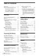
Table of Contents Precautions ......................................... 6 Notes on Installation and Usage ........ 7 Unsuitable Installation ................. 7 Usage in High Altitude ................. 8 Unsuitable Conditions .................. 9 Overview About the Supplied Manuals ............ 10 Features ............................................ 11 Location and Function of Controls (Main Unit) ................................... 13 Top/Front/Side ............................ 13 Rear/Side/Bottom ......
“Side Shot” (VPL-CX125/CX155/ CW125 only) and “V Keystone” Adjustments ..................................63 Dimensions .......................................65 Index .................................................
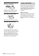
Precautions On safety • Check that the operating voltage of your unit is identical with the voltage of your local power supply. If voltage adaptation is required, consult with qualified Sony personnel. • Should any liquid or solid object fall into the cabinet, unplug the unit and have it checked by qualified Sony personnel before operating it further. • Unplug the unit from the wall outlet if it is not to be used for several days. • To disconnect the cord, pull it out by the plug.
with a cloth lightly dampened with mild detergent solution, followed by wiping with a soft dry cloth. • Use of alcohol, benzene, thinner or insecticide may damage the finish of the cabinet or remove the indications on the cabinet. Do not use these chemicals. • If you rub on the cabinet with a stained cloth, the cabinet may be scratched. • If the cabinet is in contact with a rubber or vinyl resin product for a long period of time, the finish of the cabinet may deteriorate or the coating may come off.
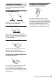
Subject to direct cool or warm air from an air-conditioner Installing in such a location may cause malfunction of the unit due to moisture condensation or rise in temperature. Near a heat or smoke sensor Malfunction of the sensor may be caused. Very dusty, extremely smoky Avoid installing the unit in a very dusty or extremely smoky environment. Otherwise, the air filter will become obstructed, and this may cause a malfunction of the unit or damage it.
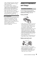
Unsuitable Conditions Do not use the Security bar for transporting or installation Do not use the unit under the following conditions. Do not topple the unit Avoid using as the unit topples over on its side. It may cause malfunction. Do not tilt right/left Use the Security bar at the side of the projector for a purpose of preventing theft, by attaching a commercially available theft prevention cable for example.
B Overview About the Supplied Manuals The following manuals and softwares are supplied with the projector. On Macintosh system, you can read only the Operating Instructions. Manuals Safety Regulations (separately printed manual) This manual describes important notes and cautions to which you have to pay attention when handling and using this projector.
Features High brightness, high picture quality High picture quality VPL-CX100/CX120/CX125/CX150/ CX155 Three super-high-aperture 0.79-inch XGA panels with approximately 790,000 effective pixels produce a resolution of 1024 × 768 dots (horizontal/vertical) for RGB input, and 750 horizontal TV lines for video input. VPL-CW125 Three super-high-aperture 0.
Other Convenient Functions • Low fan noise makes your presentation comfortable • On-screen menu in 15 languages • Picture/Audio muting • Freeze • Lamp mode switching function • Low power consumption in standby • Security bar About Trademarks • Adobe Acrobat is a trademark of Adobe Systems Incorporated. • Windows is a registered trademark of Microsoft Corporation in the United States and/or other countries.
Location and Function of Controls (Main Unit) 4 Overview Top/Front/Side 1 5 2 3 6 Rear/Side/Bottom 0 7 qa NETW INPU ORK TC RG B INPU MO NIT T A AUDI O OR OUTP RG UT AUDIO B INP S VID EO UT B VID VID EO EO AU IN DIO qs RS-23 REMO2C TE qd qf 6 8 qg 9 qh a Lens Remove the lens cap before projection. b Front remote control detector c Air filter cover Note To maintain optimal performance, clean the air filter whenever you replace the lamp.
d Control panel/Indicator For details, see “Control Panel” on page 15. e Ventilation holes (exhaust) f Adjuster adjustment button For details, see “Using the adjuster” on page 27. g Lamp cover h Ventilation holes (intake) i Adjusters j Rear remote control detector k Connector/Connector Panel For details, see “Connector Panel” on page 16. l Zoom ring Adjusts the picture size. m Focus ring Adjusts the picture focus. n Security lock Connects to an optional security cable (from Kensington).
Control Panel 1 3 ON/ STANDBY 4 INPUT a LAMP/COVER indicators Flashes in orange under the following conditions: • A reception rate of 2 flashes when the lamp cover or air filter cover is not secured firmly. • A reception rate of 3 flashes when the lamp has reached the end of its life or reaches a high temperature. For details, see page 51. b ON/STANDBY indicator Lights up or flashes under the following conditions: – Lights in red when the AC power cord is plugged into a wall outlet.
f MENU key h PIC MUTING key Displays the on-screen menu. Press again to clear the menu. Cuts off the picture. Press again to restore the picture. g PUSH ENTER/v/V/b/B (Arrow) keys Used to enter the settings of items in the menu system, select a menu, or make various adjustments.
AUDIO jack (stereo minijack) To listen to sound output from a computer, connect via this jack to the audio output of the computer. d AC IN socket e OUTPUT MONITOR connector (HD D-sub 15-pin, female) Connect to the video input connector of the monitor. Outputs signals from the selected channel and computer signals only from among the signals from the INPUT A or INPUT B. AUDIO jack (stereo minijack) Connects to external active speakers.
c AIR SHOT key Displays the Network Presentation Home. For details, see Operating Instructions for Network (stored on the CD-ROM). d APA (Auto Pixel Alignment) key Automatically adjusts a picture to its clearest while a signal is input from a computer. For details, see “Smart APA” in “The Function Menu” on page 39. e ENTER key f RESET key Resets the value of an item to its factory preset value or returns the enlarged image with D ZOOM key to its original size.
To install batteries 1 Push and slide the lid to open it, then install the two size AA (R6) batteries (supplied) with the correct polarity. Be sure to install the battery from the # side. The keys that have the same names as those on the control panel function identically. 1 2 3 4 5 6 7 8 9 0 APA qa qs INPUT KEY STONE /TILT LENS AUTO FOCUS Overview While pressing the lid, slide it.
h PIC MUTING key i D ZOOM (Digital Zoom) +/– key Enlarges the image at a desired location on the screen. j Infrared transmitter k ?/1 (On/Standby) key Face the + side up. l v/V/b/B (Arrow) keys m ENTER key n MENU key o VOLUME +/– keys p AUDIO MUTING key Press to temporarily cut off the audio output from the speaker and from the AUDIO jack of the OUTPUT. Press again or press the VOLUME + key to restore the sound. Before using the Remote Commander Pull out the clear film from the lithium battery holder.
B Projecting the Picture Installing the Projector The distance between the lens and the screen varies depending on the size of the projected image. Use the following table as a guide. Screen Projecting the Picture Distance between the screen and the center of the lens VPL-CX100/CX120/CX125/CX150/CX155 (When an XGA signal is input) Unit: m (feet) Projected image size (diagonal) (inches) 40 60 80 100 120 150 180 200 250 300 Minimum Distance 1.2 (3.9) 1.8 (5.9) 2.4 (7.9) 3.0 (9.
There may be a slight difference between the actual value and the design value shown in the table above. Notes for VPL-CW125 only • When “Aspect” on the Signal menu is set to other than “Full 2”, black bands appear at the top and bottom or right and left of the screen. • When “Aspect” in the Signal menu is set to “4:3”, the projected image size (diagonal) will be approximately 84 % of “Full 2” size.
Connecting the Projector When you connect the projector, make sure to: This section describes how to connect the projector to a computer. For more information, refer to the computer’s instruction manual. To connect a computer Side RGB NETWORK INPUT C RGB AUDIO MONITOR AUDIO OUTPUT S VIDEO AUDIO INPUT B INPUT A VIDEO VIDEO IN AUDIO RS-232C REMOTE For VPL-CX125/CX155/CW125, when connecting to a LAN using a LAN cable, see “Operating Instructions for Network” stored on the CD-ROM.
CX155) or WXGA (VPL-CW125) for the external monitor. • If you set your computer, such as a notebook computer, to output the signal to both your computer’s display and the external monitor, the picture of the external monitor may not appear properly. Set your computer to output the signal to only the external monitor. For details, refer to the operating instructions supplied with your computer. Connecting a VCR This section describes how to connect the projector to a VCR.
To connect to a video GBR/ Component output connector Side RGB NETWORK INPUT C AUDIO RGB INPUT A MONITOR AUDIO OUTPUT S VIDEO AUDIO INPUT B VIDEO VIDEO IN AUDIO RS-232C REMOTE Projecting the Picture to video GBR/ component output to audio output (L) to audio output (R) VCR A Stereo audio connecting cable (not supplied) (Use a no-resistance cable.
Projecting LAMP/ COVER 2 4 ON/ STANDBY INPUT KEYSTONE MENU PUSH ENTER PIC MUTING NET WO INPU RK TC RGB INPU T A AUD IO MON ITOR LAMP/ COVER ON/ STANDBY INPUT KEYSTONE MENU PUSH ENTER OUT PUT AUD IO PIC MUTING RGB S VIDE O VIDE VIDE O O INPU T B AUD IO IN AUD IO RSREM232C OTE ON/STANDBY indicator Front remote control detector 7 1 COMMAND OFF ON INPUT INPUT INPUT INPUT INPUT AIR SHOT VIDEO S VIDEO A D B E MENU C 6 2 4 APA 2 4 INPUT KEY STONE /TILT LENS APA AUTO FOCU
To operate with the Control Panel or the Remote Commander of VPL-CX100/CX120/CX150 Each time you press the INPUT key, the input signal switches as follows: all-in-one LCD type, you may have to switch the computer to output to the projector by pressing certain keys (e.g., , etc.), or by changing your computer’s settings. or and To input from Press INPUT to display Computer, Component, Video GBR etc. connected to the INPUT A connector Input-A Computer, etc.
adjustment is performed at the same time. If you do not want to perform the automatic keystone adjustment, set the “V Keystone” to “Manual.” (See page 41.) • If you set the “V Keystone” to “Auto,” the “V Keystone” correction is automatically adjusted. However, it may not be perfectly adjusted depending on the room temperature or the screen angle. In this case, adjust it manually. Press the KEYSTONE key to “V Keystone” displays on the screen, and adjust the value with the v/V/b/B keys.
B Convenient Functions Selecting the Menu Language You can select one of fifteen languages for displaying the menu and other on-screen displays. The factory setting is English.
The selected menu appears. Security Lock The projector is equipped with a security lock function. When you turn the power of the projector on, you are required to input the previously set password. If you do not input the correct password, you will not be able to project the picture. Notes 5 Press the v or V key to select “Language,” then press the B or ENTER key.
Enter the password on this screen. Note If you call the customer service center because you have forgotten the password, you will need to be able to verify the projector’s serial number and your identity. (This process may differ in other countries/regions.) Once your identity has been confirmed, we will provide you with the password. 3 Enter the password again to confirm. Convenient Functions When “Security Lock enabled!” is displayed on the menu screen, the setting for security lock is completed.
Other Functions By pressing the + key repeatedly, the image size (ratio of enlargement: max. 4 times) increases. Direct Power On/Off Function If you will be using a circuit breaker to turn the power for the entire system on and off, set the direct power on function to “On.” When you turn off the power, you can also just unplug the power cord without pressing the ?/1 key. Use the arrow key (v/V/b/B) to scroll the enlarged image.
Controlling the Computer Using a Presentation Tool, RM-PJPK1 (not supplied) (When Using the Network Presentation Function) (VPLCX125/CX155/CW125 only) When you are using the network presentation function to project the picture from a computer, you can perform some operations for a slide show using a presentation tool (not supplied). The following keys on the presentation tool are usable. Function LASER* Emits a laser beam. G SLIDE g Changes the slides in the forward/backward direction.
B Adjustments and Settings Using a Menu Pop-up menu Using a MENU Items that can be set The projector is equipped with an on-screen menu for making various adjustments and settings. Some of the adjustable/setting items are displayed in a pop-up menu, in a setting menu or adjustment menu with no main menu, or in the next menu window. If you select an item name followed by an arrow (B), the next menu window with the setting items appears.
To clear the menu Press the MENU key. The menu disappears automatically if a key is not pressed for one minute. To reset items that have been adjusted Select the item that you want to reset, and press the RESET key on the Remote Commander. “Complete!” appears on the screen and the setting of the item that you have selected is reset to its factory preset value. Items that can be reset are: • “Contrast,” “Brightness,” “Color,” “Hue” and “Sharpness” on the “Adjust Picture...” menu of the Picture menu.
The Picture Menu The Picture menu is used for adjusting the picture or volume. Picture Picture Mode: Adjust Picture Standard Volume: 30 Signal Picture Signal Function Function Installation Installation Setup Setup Information Adjust Picture Contrast: Brightness: Sharpness: Gamma Mode: Color Temp.: Standard 80 50 50 Graphics Low: Information Sel: Set: Exit: Sel: Set: Back: Exit: Setting items Functions Picture Mode Selects the picture mode.
The Signal Menu The Signal menu is used to adjust the input signal. Adjust Signal...
Setting items Functions Aspect (When the PC signal is input) You can set the aspect ratio of the picture to be Set according to displayed for the current input signal. This item is the input signal enabled only when an PC signal (preset memory numbers 21 to 63) is input. • Full 1: Displays a picture vertically or horizontally to fill the screen without changing the aspect ratio of the original picture. • Full 2:The original image is projected fully in the window.
The Function Menu The Function menu is used for changing the settings of the projector. Functions The APA (Auto Pixel Alignment) automatically On adjusts “Dot Phase,” “H Size” and “Shift” on the Signal menu for the input signal from a computer. • On: When a signal is input from a computer, the APA functions automatically so that the picture can be seen clearly.
Setting items Functions Power Saving Selects the Power Saving mode. Off • Lamp off: The lamp goes off if no signal is input for 10 minutes. The lamp lights again when a signal is input or any key is pressed. • Standby: The projector goes into Standby mode if no signal is input for 10 minutes. To use it, turn on the power again. • Off: The projector does not go into Power Saving mode.
The Installation Menu The Installation menu is used for changing the settings of the projector. Picture Signal Function Installation Setup V Keystone: Side Shot: Image Flip: Background: Lamp Mode: IR Receiver: ID Mode: Direct Power On: High Altitude Mode: Auto 0 Off Blue Standard Front & Rear All Off Off Information Sel: Set: Exit: Functions V Keystone Corrects the trapezoidal distortion caused by the projection Auto angle.
Setting items Functions ID Mode (VPL-CX125/ CX155/CW125 only) All Assigns an ID number (1 to 3) to the projector when you want control two or more projectors individually with the supplied Remote Commander. When this item is set to “1,” you can control the projector with the Remote Commander with the ID MODE key set to “1.” When it is set to “All,” you can control all the projectors with the Remote Commander independently of the ID MODE keys of the Remote Commander.
The Setup Menu The Setup menu is used for changing the menu displays. Functions Initial setting Sets up the on-screen display. When set to “Off,” turns off the on-screen displays except for the menus, a message when the power is turned off, and warning messages. On Language Selects the language used in the menu and on-screen displays. The languages available are: English, Nederlands, Français, Italiano, Deutsch, Español, Português, , Svenska, Norsk, , , , and . English Auto Input-A Signal Sel.
The Information Menu The Information menu displays the model name, serial number, the horizontal and vertical frequencies of the input signal and the cumulated hours of usage of the lamp. Model name Serial number Memory No. (Memory number of an input signal) Signal type Setting items Functions fH Displays the horizontal frequency of the input signal. The displayed value is approximate. fV Displays the vertical frequency of the input signal. The displayed value is approximate. Memory No.
Input signals and adjustable/setting items Some of the items in the menus cannot be adjusted depending on the input signal as indicated in the following tables. The items that cannot be adjusted are not displayed in the menu.
B Maintenance Replacing the Lamp RS-2 REM 32C OTE S VIDE O VIDE VIDE O O IN AUD IO OUT PUT AUDIO MON ITOR INPU TB RGB INPU T A AUD IO RGB NET INPUWORK TC The lamp used as a light source is a consumable product. Replace this lamp with a new one in the following cases. • When the lamp has burnt out or dims • “Please replace the Lamp and clean the Filter.” appears on the screen. • The LAMP/COVER indicator flashes in red. (Repetition rate of 3 flashes) The lamp life varies depending on conditions of use.
10Select “Lamp Timer Reset”, and then press the ENTER key. 11Select “Execute” with the V key, and then press the ENTER key. Notes • Be careful not to touch the glass surface of the lamp. • The power will not turn on if the lamp is not secured properly. The Lamp Timer is initialized to 0, and “Change the Lamp and clean the Filter?” is displayed in the menu screen. Refer to page 48 for “Cleaning the Air Filter”.
Note Cleaning the Air Filter The air filter should be cleaned whenever you replace the lamp. Remove the air filter, and then remove the dust with a vacuum cleaner. The time needed to clean the air filter will vary depending on the environment or how the projector is used. 1 Turn the power off and unplug the power cord. 2 Remove the air filter cover. 3 Remove the air filter from the each claws (7 positions) on the air filter cover. Claws 48 4 Clean the air filter with a vacuum cleaner.
B Others Troubleshooting If the projector appears to be operating erratically, try to diagnose and correct the problem using the following instructions. If the problem persists, consult with qualified Sony personnel. Power Symptom Cause and Remedy The power is not turned on. • The power has been turned off and on with the ?/1 key at a short interval. c Wait for about 60 seconds before turning on the power. • The lamp cover is not secured. c Close the lamp cover securely (see page 47).
Symptom Cause and Remedy “Please check Input-A Signal Sel.” appears in spite of inputting the correct signal from INPUT A. The setting of “Input-A Signal Sel.” in the Setup menu is incorrect. c Select “Computer,” “Video GBR” or “Component” correctly according to the input signal (see page 43). On-screen display does not “Status” in the Setup menu has been set to “Off.” c Set “Status” in the Setup menu to “On” (see page 43). appear. Color balance is incorrect.
Remote Commander Symptom Cause and Remedy The Remote Commander does not work. • The Remote Commander batteries are dead. c Replace them with new batteries (see pages 19, 20). • The COMMAND ON/OFF switch is set to OFF. (VPL-CX125/ CX155/CW125 only) c Set it to ON. (page 18) • The ID number of the projector assigned in “ID Mode” in the Installation menu does not match the ID number of the ID MODE keys on the Remote Commander.
Symptom Cause and Remedy ON/STANDBY flashes in red. (Repetition rate of 6 flashes) Unplug the AC power cord from the wall outlet after the ON/ STANDBY indicator goes out, plug the power cord to the wall outlet, and then turn the projector on again. If the ON/STANDBY flashes in red and the problem persists, the electrical system has failed. c Consult with qualified Sony personnel.
Messages List Warning Messages Use the list below to check the meaning of the messages displayed on the screen. Message Meaning and Remedy High temp.! Lamp off in 1 min. The internal temperature is too high. c Turn off the power. c Check to see that nothing is blocking the ventilation holes. Frequency is out of range! • This input signal cannot be projected as the frequency is out of the acceptable range of the projector. • The resolution setting of the output signal of the computer is too high.
Specifications Optical characteristics Projection system 3 LCD panels, 1 lens, 3 primary color shutter system LCD panel VPL-CX100/CX120/CX125/ CX150/CX155: 0.79-inch XGA panel, 2,359,296 pixels (1024 × 768 × 3) VPL-CW125: 0.74-inch WXGA panel, 3,280,000 pixels (1366 × 800 × 3) Lens 1.2 times zoom lens f 23.5 to 28.2 mm/F1.75 to 2.
Input/Output Video input INPUT A OUTPUT REMOTE NETWORK (VPL-CX125/ CX155/CW125 only) RJ-45: 10BASE-T/100BASETX MONITOR OUT’: HD D-sub 15pin (female) R, G, B: Gain Unity: 75 ohms SYNC/HD, VD: 4 Vp-p (open), 1 Vp-p (75 ohms) AUDIO OUT (variable out): Stereo minijack 1 Vrms (When the volume is maximum and an input signal is 500 mVrms), output impedance 5 kilohms RS-232C: D-sub 9 pin General 372 × 90 × 298 mm (14 3/4 × 3 5/8 × 11 3/4 inches) (w/h/d) (without the projection parts) Mass Approx. 4.
AC power cord (1) CD-ROM (Operating Instructions, Application Software) (1) Quick Reference Manual (1) Safety Regulations (1) Security Label (1) Design and specifications are subject to change without notice. INPUT B connector (HD D-sub 15-pin, female) 1 R 9 2 G 10 GND 3 B 11 GND 4 GND 12 DDC/SDA 5 GND 13 HD 6 GND (R) 14 VD 7 GND (G) 15 DDC/SCL 8 GND (B) Note Always verify that the unit is operating properly before use.
Preset signals Memory Preset signal No. Video 60 Hz fH (kHz) fV (Hz) Sync SIZE 15.734 – – 1 Video 60 Hz 59.940 2 Video 50 Hz Video 50 Hz 15.625 50.000 – – 3 480/60i DTV 480/60i 15.734 59.940 S on G/Y – 4 575/50i DTV 575/50i 15.625 50.000 S on G/Y – 5 480/60p 480/60p (NTSC Progressive component) 31.470 60.000 S on G/Y – 6 575/50p 575/50p (PAL Progressive component) 31.250 50.000 S on G/Y – 7 1080/60i 1035/60i, 1080/60i 33.750 60.
Memory Preset signal No. 41 1152 × 864 42 43 44 1152 × 900 45 1280 × 960 46 47 1280 × 1024 48 49 fH (kHz) fV (Hz) Sync SIZE VESA 70 63.995 70.019 H-pos, V-pos 1472 VESA 75 67.500 75.000 H-pos, V-pos 1600 VESA 85 77.487 85.057 H-pos, V-pos 1568 SUN LO 61.795 65.960 H-neg, V-neg 1504 VESA 60 60.000 60.000 H-pos, V-pos 1800 VESA 75 75.000 75.000 H-pos, V-pos 1728 VESA 60 63.974 60.013 H-pos, V-pos 1688 SXGA VESA75 79.976 75.
Installation Diagram Floor Installation (Front Projection) Distance between the front of the cabinet and the center of the lens Front of the cabinet Wall Front of the lens 15.9 (21/32) Center of the screen Center of the lens Floor Unit: mm (inches) This section describes the examples of installing the projector on a desk, etc. See the chart on page 60 concerning the installation measurements. Installation Diagram .Others The alphabetical letters in the illustration indicate the distances below.
VPL-CX100/CX120/CX125/CX150/CX155 (When an XGA signal is input) Unit: mm (inches) PS a 40 60 80 100 120 150 180 200 1170 (46 1/8) 1770 (69 3/4) 2380 (93 3/4) 2990 (117 3/4) 3590 (141 3/8) 4500 (177 1/4) 5410 (213 1/8) 6020 7540 (237 1/16) (297) 9050 (356 3/8) M 1350 (53 1/4) 2050 (80 3/4) 2750 (108 3/8) 3450 (135 7/8) 4140 (163 1/8) 5190 (204 3/8) 6240 (245 3/4) 6940 (273 3/8) 10430 (410 3/4) x-889 (x-35) x-1067 (x-42) x-1185 x-1482 x-1778 (x-46 3/4) (x-58 3/8) (x-70 1/8) N 25
Ceiling Installation (Front Projection) 46.1 (1 7/8) 1 12.2 ( /2) 56.6 (2 1/4) 64.9 (2 5/8) Center of the Projector Center of the screen 52.7 (2 1/8) Holes for mounting a projector suspension support Center of the lens Ceiling Center of the lens OUTPUT AUDIO S VIDEO VIDEO VIDEO IN Center of the lens Hole for mounting a projector suspension support (front) 21 AUDIO S VIDEO VIDEO VIDEO IN AUDIO RS-232C REMOTE RS-232C REMOTE INPUT B AUDIO 15.9 ( /32) 1 137.
VPL-CX100/CX120/CX125/CX150/CX155 (When an XGA signal is input) Unit: mm (inches) PS 40 60 80 100 120 150 180 200 250 300 a’ N 1290 (50 25/32) 1900 (74 7/8) 2500 (98 1/2) 3110 (122 1/2) 3720 (146 1/2) 4630 (182 3/8) 5540 (218 1/4) 6140 (241 7/8) 7660 (301 5/8) 9180 (361 1/2) M 1470 (57 7/8) 2170 (85 1/2) 2870 (113 1/8) 3560 (140 1/4) 4260 (167 3/4) 5310 (209 1/8) 6360 (250 1/2) 7050 (277 5/8) 8800 (346 1/2) 10540 (415 1/8) x b+290 b+409 b+527 b+646 b+764 b+942 b+1120 b+1239
“Side Shot” (VPL-CX125/CX155/CW125 only) and “V Keystone” Adjustments With “Side Shot” (horizontal keystone adjustment) provided for the projector, you can project the picture from the side of the screen. When projecting with “Side Shot” adjustment only, you can adjust the horizontal distortion of the screen to the maximum using “Side Shot.” When projecting with both “Side Shot” and “V Keystone” (vertical keystone adjustment), you can adjust the vertical ( ) and horizontal ( ) distortion of the screen.
VPL-CX125/CX155 Input signals Video/60, Video/50, 480/60i, 575/50i, 480/60p, 575/50p 1080/60i, 1080/50i, 540/60p 720/60p, 720/50p a b a=0 0 +/–15 a≠0 or b≠0 +/–18 +/–8 b=0 +/–25 0 a=0 0 +/–13 a≠0 or b≠0 +/–18 +/–8 b=0 +/–25 0 a=0 0 +/–13 a≠0 or b≠0 +/–18 +/–6 b=0 +/–25 0 PC (Preset signal No.21 to 49, 51 to 60), Air Shot, except SXGA+ a=0 0 +/–11 a≠0 or b≠0 +/–18 +/–6 b=0 +/–25 0 PC (Preset signal No.
Dimensions Front 64.9 (2 5/8) Center of the lens 13 (17/32) 27 (1 1/8) 61.2 (2 1/2) Remote control detector (Front) 141 (5 5/8) 24 (31/32) Unit: mm (inches) Top 34 (1 3/8) DATA PROJECTOR ON/ STANDBY INPUT KEYSTONE MENU PUSH ENTER PIC MUTING 5.3 (7/32) LAMP/ COVER 123 (4 7/8) 263 (10 3/8) 298 (11 3/4) .
Side Center of the lens 1.7 (3/32) 88 (3 1/2) 190 (7 1/2) 61.2 23 (29/32) (2 1/2) 90 (3 5/8) 63 (2 1/2) 15.9 (21/32) 260 /32) 9 (3/8) 16 (21/32) 103 (4 1/8) (10 1/4) Projector suspension support mounting surface VPL-CX125/CX155/CW125 only 172 (6 7/8) 78 (3 1/8) 17 (11/16) 18 (23/32) AUDIO S VIDEO VIDEO VIDEO IN AUDIO RS-232C REMOTE 35 (1 7/16) 26 (1 1/16) 40 20 (13/16) 31 (1 1/4) 30 (1 3/16) (1 5/8) 18 (23/32) 23 (29/32) 20 (13/16) 22.
Rear 154 (6 1/8) 152.5 (6 1/8) Remote control detector (Rear) 15 (19/32) 326 (12 7/8) 49 (1 15/16) 24 (31/32) 66 (2 5/8) Unit: mm (inches) Bottom 148 (5 7/8) 32 (1 5/16) 174 (6 7/8) 104.5 (4 1/8) .Others 275 (10 7/8) 124 (5) 137.3 (5 1/2) Holes for mounting a projector suspension support 56.6 (2 1/4) 46.1 (1 7/8) 12.
Index Floor installation ..................................59 Installing the projector .............................21 IR Receiver ..............................................41 A L Adjuster ................................................... 27 Air filter ................................................... 48 Aspect ............................................... 37, 38 Auto Input Search ................................... 39 B Background ............................................. 41 Brightness .
S Screen size ...............................................21 Security bar .......................................14, 66 Security Lock ..........................................40 Security lock ............................................14 Serial number ..........................................44 Sharpness .................................................36 Shift .........................................................37 Side Shot ...........................................41, 63 Signal type ..........
Sony Corporation