
Operation Manual


61
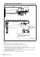
Installation Diagram
Others
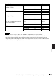
a’(N) = {(SS × 23.306/0.7874)+4.7574} × 1.025
a’(M) = {(SS ×
28.188/0.7874)+75.509} × 0.975
x = b + (SS/0.7874 × 4.667+53.2)
The installation measurements and their calculation method for each lens are shown above.
The alphabetical letters in the charts and calculation methods indicate the following.
SS: screen size measured diagonally (inches)
a’: distance between the hole (front) for mounting a projector suspension support on bottom
surface of this projector and the center of the screen
b: distance between the projector suspension support mounting surface on bottom of this
projector and the ceiling
x: distance between the center of the screen and the ceiling
N: minimum
M: maximum
Unit: mm (inches)
SS 40 60 80 100 120 150 180 200 250 300
a’ N 1290
(50
3
/
4
)
1900
(74
7
/
8
)
2500
(98
1
/
2
)
3110
(122
1
/
2
)
3720
(146
1
/
2
)
4630
(182
3
/
8
)
5540
(218
1
/
4
)
6140
(241
7
/
8
)
7660
(301
5
/
8
)
9180
(361
1
/
2
)
M 1470
(57
7
/
8
)
2170
(85
1
/
2
)
2870
(113
1
/
8
)
3560
(140
1
/
4
)
4260
(167
3
/
4
)
5310
(209
1
/
8
)
6360
(250
1
/
2
)
7050
(277
5
/
8
)
8800
(346
1
/
2
)
10540
(415
1
/
8
)
x b+290
(b+11
1
/
2
)
b+409
(b+16
1
/
8
)
b+527
(b+20
3
/
4
)
b+646
(b+25
1
/
2
)
b+764
(b+30
1
/
8
)
b+942
(b+37
1
/
8
)
b+1120
(b+44
1
/
8
)
b+1239
(b+48
7
/
8
)
b+1535
(b+60
1
/
2
)
b+1831
(b+72
1
/
8
)
b Free