4-095-440-12 (1) Data Projector Data Projector VPL-CS6/VPL-CX6/VPL-EX1 Operating Instructions GB Mode d’emploi FR Manual de instrucciones ES VPL-CS6 VPL-CX6 VPL-EX1 © 2003 Sony Corporation
WARNING To prevent fire or shock hazard, do not expose the unit to rain or moisture. To avoid electrical shock, do not open the cabinet. Refer servicing to qualified personnel only. The number below is for FCC related matters only. Declaration of Conformity Trade Name: SONY Model No.: VPL-CS6/VPL-CX6/VPL-EX1 Responsible Party: Sony Electronics Inc. Address: 680 Kinderkamack Road, Oradell, NJ 07649 U.S.A. Telephone No.: 201-930-6972 This device complies with Part 15 of the FCC Rules.
For the customers in Canada This Class B digital apparatus complies with Canadian ICES-003. Voor de klanten in Nederland Gooi de batterij niet weg maar lever deze in als klein chemisch afval (KCA). The socket-outlet should be installed near the equipment and be easily accessible.
GB 4
Table of Contents Overview Precautions .........................................6 Adjustments and Settings Using the Menu Notes on Installation .......................... 7 Using the MENU ............................. 32 Unsuitable Installation .................. 7 Unsuitable Conditions .................. 7 Usage in High Altitude ................. 8 Features .............................................. 8 The PICTURE SETTING Menu ..... 34 Location and Function of Controls .
B Overview Precautions light-reflecting material. If the floor and walls are of reflecting material, it is recommended that the carpet and wall paper be changed to a dark color. On safety • Check that the operating voltage of your unit is identical with the voltage of your local power supply. • Should any liquid or solid object fall into the cabinet, unplug the unit and have it checked by qualified personnel before operating it further.
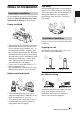
Notes on Installation Unsuitable Installation Avoid installing the unit in a location where there is a lot of dust; otherwise, the air filter will be obstructed. The dust blocking the air through the filter may cause raising the internal heat of the projector. Clean it up periodically. Poorly ventilated Unsuitable Conditions Do not use the projector under the following conditions. • Allow adequate air circulation to prevent internal heat build-up. Do not place the unit on surfaces (rugs, blankets, etc.
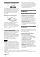
Tilting the unit to the right or left • When using a screen with an uneven surface, stripes pattern may rarely appear on the screen depending on the distance between the screen and the projector or the zooming magnifications. This is not a malfunction of the projector. Avoid tilting the unit to an angle of 15°, and avoid installing the unit in any way other than placing on the floor or suspending from the ceiling. Such installation may cause color shading or shorten the lamp life excessively.
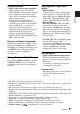
Easy presentation Easy-to-use Remote Commander The Remote Commander is equipped with various convenient keys, including the D ZOOM key for zooming in on the image and the FREEZE key for keeping the image projected even if the equipment is disconnected. Memory Stick slot (VPL-CX6 only) By inserting a Memory Stick into the builtin Memory Stick slot, you can make the presentation easily without connecting the computer.
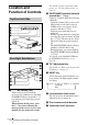
Location and Function of Controls For details on steps for turning off the power, see “To turn off the power” on page 29. 2 ON/STANDBY indicator (located around the I / 1 key) Lights up or flashes under the following conditions: – Lights in red when a AC power cord is plugged into a wall outlet. Once in standby mode, you can turn on the projector with the I / 1 key. – Lights in green when the power is turned on.
8 Control/Connector panel For details, see “Control Panel” and “Connector Panel” on page 12. How to use the powered tilt adjuster To adjust the height Adjust the height of the projector as follows: 0 Ventilation holes (intake) 1 Overview 9 Rear remote control detector Press the I / 1 key The lens protector opens, and the powered tilt adjuster rises automatically. The adjuster stops at its previously adjusted position.
5 TEMP (Temperature)/FAN indicator Control Panel Lights up or flashes under the following conditions: – Lights up when temperature inside the projector becomes unusually high. – Fashes when the fan is broken. POWER SAVING INPUT A ACCESS MENU PUSH ENTER AUDIO For details on the TEMP/FAN indicator, see page 46.
2 USB connector (USB plug for upstream, 4-pin) The keys that have the same names as those on the control panel function identically. For VPL-CS6/VPL-CX6 qg qf qd FREEZE MS SLIDE I / 1 qs KEYSTONE INPUT 3 Memory Stick slot (VPL-CX6 only) The Memory Stick can be inserted. Never insert an object other than the Memory Stick. APA qa MENU 0 PIC When listening to sound output from the computer, connect to the audio output of the computer.
• You can cancel the adjustment by pressing the APA key again while “Adjusting” appears on the screen. • The picture may not be adjusted properly depending on the kinds of input signals. • Adjust the items “Dot Phase,” “H Size” and “Shift” in the INPUT SETTING menu when you adjust the picture manually. 3 PIC MUTING key Used to mute the picture temporarily. Press again to restore the picture. 4 ENTER key 5 Keys emulate a mouse Functions like a mouse of a computer connected via USB with the projector.
To install batteries 1 Push and slide to open the lid, then install the two size AA (R6) batteries (supplied) with the correct polarity. Be sure to install the battery from the # side. Enlarges the image at a desired location on the screen. +: Pressing the + key once displays the icon. This icon indicates the point you want to enlarge. Use an arrow key (M/ m/
Before using the Remote Commander Pull out the clear film from the lithium battery holder. To replace battery 1 Release the lock of the lithium battery holder by picking it, and pull out the holder from the Remote Commander. 2 Install the lithium battery. + side facing upward GB 16 Location and Function of Controls 3 Put the lithium battery holder back into the Remote Commander. Notes on the lithium battery • Keep the lithium battery out of the reach of children.
B Setting Up and Projecting Installing the Projector This section describes how to install the projector. The distance between the lens and the screen varies depending on the size of the screen. Use the following table as a guide. Setting Up and Projecting Distance between the screen and the center of the lens VPL-CS6/VPL-CX6 Unit: m (feet) Screen size (inches) Minimum Distance 40 60 80 100 120 150 1.2 (3.9) 1.9 (6.2) 2.5 (8.2) 3.2 (10.5) 3.8 (12.5) 4.7 (15.4) Maximum 1.5 2.3 3.0 3.8 4.6 5.
Connecting the Projector When you connect the projector, make sure to: • Turn off all equipment before making any connections. • Use the proper cables for each connection. • Insert the cable plugs firmly; loose connections may increase noise and reduce performance of picture signals. When pulling out a cable, be sure to pull it out from the plug, not the cable itself To connect the projector, refer to the illustrations on the next and the following pages.
To connect an IBM PC/AT compatible computer Left side POWER SAVING INPUT A AUDIO ACCESS Computer MENU to monitor output PUSH ENTER PRO VIDEO S VIDEO TEMP/FAN LAMP/COVER HD D-sub 15-pin cable (supplied) Stereo audio connecting cable (not supplied)a) to audio output Setting Up and Projecting USB cable (supplied only VPL-CS6/CX6) (Connect the USB cable to use a wireless mouse or the Projector Station.) to USB connector a) Use a no-resistance cable.
To connect a Macintosh computer To connect a Macintosh computer equipped with video output connector of a type having two rows of pins, use a commercially available plug adaptor. When you connect a USB capable Macintosh computer using the USB cable to the projector, wireless mouse functions become available. Note The supplied software does not run on Macintosh computer.
To connect a 15k RGB/Component equipment SMF-402 Signal Cable (not supplied) HD D-sub 15-pin (male) ↔ 3 × phono jack Left side POWER SAVING INPUT A AUDIO ACCESS MENU PUSH ENTER PRO VIDEO S VIDEO TEMP/FAN Stereo audio connecting cable (not supplied)a) LAMP/COVER a) Use a no-resistance cable. Setting Up and Projecting to audio output to RGB/ component output 15k RGB/Component equipment Notes • Set the aspect ratio using “Wide Mode” in the INPUT SETTING menu according to the input signal.
Selecting the Menu Language You can select one of thirteen languages for displaying the menu and other onscreen displays. The factory setting is English. To change the menu language, proceed as follows: POWER SAVING INPUT A MENU PUSH ENTER PRO AUDIO ACCESS VIDEO S VIDEO TEMP/FAN LAMP/COVER Front remote control detector FREEZE MS SLIDE I / 1 KEYSTONE INPUT MENU APA PIC ENTER MUTING For VPL-CS6/CX6 For VPL-EX1 1 Open the connector panel, then plug the AC power cord into a wall outlet.
4 Press the M or m key to select the MENU SETTING menu, then press the , or ENTER key. The selected menu appears. Input A : : A : : Setting Up and Projecting 5 Press the M or m key to select “Language,” then press the , or ENTER key. Input A : : : : 6 Press the M, m, < or , key to select a language, then press the ENTER key. The menu changes to the selected language. To clear the menu Press the MENU key. The menu disappears automatically if a key is not pressed for one minute.
Projecting 5 TILT Rear remote control detector 6 7 2 ON/STANDBY indicators 4 FREEZE MS SLIDE I / 1 KEYSTONE INPUT MENU APA PIC ENTER MUTING For VPL-CS6/CX6 For VPL-EX1 1 Open the connector panel, plug the AC power cord into a wall outlet, then connect all equipment. The ON/STANDBY indicator lights in red and the projector goes into standby mode. 2 Press the I / 1 key. The ON/STANDBY indicator lights in green and the Intelligent Auto-setup starts.
F7 or Fx Fn 4 Press the INPUT key to select the input source. Press INPUT to display Computer connected to the INPUT A connector INPUT A Memory Stick inserted to the Memory Stick slot (VPL-CX6 only) MS Video equipment connected to the VIDEO input connector VIDEO Video equipment connected to the S VIDEO input connector S VIDEO Setting Up and Projecting To input from Smart APA (Auto Pixel Alignment) adjusts the picture of the connected equipment so that it is projected clearly.
Note The auto V keystone adjustment may not correct the trapezoidal distortion perfectly, depending on the room temperature or the screen angle. In this case, adjust it manually. Press the KEYSTONE key (VPL-CS6/CX6) or the D KEYSTONE key (VPL-EX1) on the Remote Commander until “V Keystone” appears on the screen, and adjust the value with the M/m/
To Use the security lock 1 Press the MENU key and then, in the INSTALL SETTING menu, turn on the “Security Lock” setting. 2 Enter the password. Use the MENU, M/m/
4 The setting for security lock is completed. INSTALL SETTING X Input A Tilt... V Key s t o n e : Au t o . . . I m ag e F l i p : Off B a ck g ro u n d : Blue Lamp Mode: S t a n d a rd High Altitude Mode: O f f S e c u r i t y L o ck : On S e c u r i t y L o ck e n a bl e d ! 5 Turn the main power off and disconnect the AC power cord. The security lock is set to on, then it becomes effective. The screen for entering the password is displayed when the power is turned on the next time.
To turn off the power 1 Press the I / 1 key. “POWER OFF? Please press I / 1 key again.” appears to confirm that you want to turn off the power. Note A message disappears if you press any key except the I / 1 key, or if you do not press any key for five seconds. 2 Press the I / 1 key again. 3 Setting Up and Projecting The powered tilt adjuster is put away in the projector and the lens protector closes.
Effective Tools for Your Presentation To enlarge the image (Digital Zoom function) You can select a point in the image to enlarge. This function works when a signal from a computer is input, or when a still picture (except a movie picture) stored in a Memory Stick is projected (VPL-CX6 only). This function does not work when a video signal is input. 1 Project a normal image, and press the D ZOOM + key on the Remote Commander. The digital zoom icon appears in the center of the image.
To freeze the image projected (Freeze function) Press the FREEZE key. “Freeze” appears when the key is pressed. This function works when a signal from a computer is input or when a still picture stored in a Memory Stick is projected (VPL-CX6 only). To restore the original screen, press the FREEZE key again.
B Adjustments and Settings Using the Menu Using the MENU 1 The menu appears. The menu presently selected is shown as a yellow button. The projector is equipped with an on-screen menu for making various adjustments and settings. The setting items are displayed in a pop-up menu or in a sub menu. If you select an item name followed by dots (...), a sub menu with setting items appear. You can change the tone of the menu display and the menu language displayed in the on-screen menu.
4 Make the setting or adjustment on an item. • When changing the adjustment level: To increase the number, press the M or , key. To decrease the number, press the m or < key. Press the ENTER key to restore the previous screen. • When changing the setting: Press the M or m key to change the setting. Press the ENTER or < key to restore the previous screen. About the menu display You can set the display position of the menu, intensity of the background picture and tone of the menu items as you like.
The PICTURE SETTING Menu Adjust Picture... When the video signal is input PICTURE SETTING Video ADJUST PICTURE The PICTURE SETTING menu is used for adjusting the picture or volume. Items that cannot be adjusted depending on the input signal are not displayed in the menu. Contrast: Brightness: Color: Hue: Sharpness: C o l o r Te m p . : S t a n d a rd 80 50 50 50 Middle Low For details on the unadjustable items, see page 51.
Sharpness Selects the picture sharpness from among “High,” “Middle” and “Low.” The “High” setting makes the picture sharp; the “Low” setting makes it soft. RGB Enhancer Adjusts the picture sharpness when RGB signals are input. The higher the setting, the sharper the picture. The lower the setting, the softer the picture. Gamma Mode The INPUT SETTING menu is used to adjust the input signal. Items that cannot be adjusted depending on the input signal are not displayed in the menu.
by switching to the wide mode may constitute an infringement of the rights of authors or producers, which are legally protected. Adjust Signal... Menu Items (Only when the RGB signal is input) INPUT SETTING Input A SIGNAL SETTING Dot Phase: H Size: Shift: 24 1504 H: 181 V: 34 Scan Converter Converts the signal to display the picture according to the screen size. On: Displays the picture according to the screen size. The picture will lose some clarity.
Since the data is recalled from the preset memory about the following signals, you can use these preset data by adjusting “H Size.” Make fine adjustment by adjusting “Shift.” Signal Memory No. SIZE Super Mac-2 23 1312 SGI-1 23 1320 Macintosh 19" 25 1328 The following are for the VPL-CX6/EX1 only. 27 1456 Sony News 36 1708 PC-9821 1280 × 1024 36 1600 WS Sunmicro 37 1664 Note When the aspect ratio of input signal is other than 4:3, a part of the screen is displayed in black.
Input-A Signal Sel. Selects the computer, component or video GBR signal input from the INPUT A connector. Note If the setting is not correct, the color of the picture becomes strange or “Please check Input-A Signal Sel.” appears on the screen and the picture is not displayed. The MENU SETTING Menu The MENU SETTING menu is used for changing the settings of the projector.
The INSTALL SETTING Menu The INSTALL SETTING menu is used for changing the settings of the projector. INSTALL SETTING Input A Tilt... V Key s t o n e : Au t o I m ag e F l i p : Off B a ck g ro u n d : Blue Lamp Mode: S t a n d a rd High Altitude Mode: O f f S e c u r i t y L o ck : Off Image Flip Flips the image on the screen horizontally and/or vertically. Off: The image does not flip. HV: Flips the image horizontally and vertically. H: Flips the image horizontally. V: Flips the image vertically.
The INFORMATION Menu The INFORMATION menu displays the horizontal and vertical frequencies of the input signal and the used time of the lamp. I N F O R M AT I O N Input A fH: fV: 48.47kHz 60.00Hz No.23 1024x768 Lamp Timer: 0H Memory number of a input signal Signal type Menu Items fH Displays the horizontal frequency of the input signal. The displayed value is approximate. fV Displays the vertical frequency of the input signal. The displayed value is approximate.
B Maintenance Maintenance 2 Open the lamp cover by loosening a screw with the Phillips screwdriver (supplied with the Projector Lamp). Replacing the Lamp Replace the lamp with a new one in the following case. • When the lamp has burnt out or dims • “Please replace the LAMP.” appears on the screen • The LAMP/COVER indicator lights up The lamp life varies depending on conditions of use. Use LMP-C150 Projector Lamp as the replacement lamp.
4 Insert the new lamp all the way in until it is securely in place. Tighten the screws. Fold the handle. Disposal of the used lamp As the used lamp contains Mercury, dispose of the lamp according to local, state or federal laws. As the materials used in this lamp are similar to those of a fluorescent lamp, you should dispose of a used projector lamp in the same way as a fluorescent lamp. Cleaning the Air Filter The air filter should be cleaned every 300 hours.
4 Remove the air filter. 5 Wash the air filter with a mild detergent solution and dry it in a shaded place. 6 Attach the air filter and replace the cover. Notes Maintenance • If you neglect to clean the air filter, dust may accumulate, clogging it. As a result, the temperature may rise inside the unit, leading to a possible malfunction or fire. • If the dust cannot be removed from the air filter, replace the air filter with the supplied new one.
Troubleshooting If the projector appears to be operating erratically, try to diagnose and correct the problem using the following instructions. If the problem persists, consult with qualified Sony personnel. Power Symptom Cause and Remedy The power is not turned on. • The power has been turned off and on with the I / 1 key at a short interval. c Wait for about 90 seconds before turning on the power (see page 29). • The lamp cover is detached. c Close the lamp cover securely (see page 41).
Symptom Cause and Remedy The picture from INPUT A • Setting of “Input-A Signal Sel.” in the SET SETTING menu is connector is colored incorrect. strange. c Select “Computer,” “Video GBR” or “Component” correctly according to the input signal (see page 38). “Please check Input-A • Setting of “Input-A Signal Sel.” in the SET SETTING menu is Signal Sel.” appears in incorrect.
Remote Commander Symptom Cause and Remedy The Remote Commander does not work. • The Remote Commander batteries are dead. c Replace with a new battery (see page 15, 16). Others Symptom Cause and Remedy The LAMP/COVER indicator flashes. • The lamp cover or the air filter cover is detached. c Attach the cover securely (see page 42 and 43). • The lens protector does not open due to a problem. c Consult with qualified Sony personnel.
Caution Messages Use the list below to check the meaning of the messages displayed on the screen. Message Meaning and Remedy Not applicable! • You have pressed the wrong key. c Press the appropriate key.
B Other On the emergency mode 2 Slide switch A in the slit in front of the adjuster in the direction of the arrow (toward the front panel of the projector) with the small minus screwdriver. The lens protector and the tilt adjuster are switched to the emergency mode. Before performing the following procedure, try to diagnose the problem using the instructions described in "Troubleshooting" (page 44). If the problem persists, read and following procedure thoroughly and then proceed.
150-inch: 5.9 to 7.2 m (19.4 to 23.6 feet) Specifications Optical characteristics 1) ANSI lumen is a measuring method of American National Standard IT 7.228. Electrical characteristics Color system NTSC3.58/PAL/SECAM/ NTSC4.
INPUT A HD D-sub15-pin (female) Analog RGB/component: R/R-Y: 0.7 Vp-p ±2 dB (75 ohms terminated) G: 0.7 Vp-p ±2 dB (75 ohms terminated) G with sync/Y: 1 Vp-p ±2 dB sync negative (75 ohms terminated) B/B-Y: 0.
Pin assignment INPUT A connector (HD D-sub 15-pin, female) Input signals and adjustable/ setting items Adjust Picture... menu Item Input signal Video or S video (Y/C) Com- Video Component GBR puter B&W z 1 R/R-Y 9 N.C. Contrast z z z 2 G/Y 10 GND Brightness z z z z z 3 B/B-Y 11 GND Color z z z – – 4 GND 12 DDC/SDA Hue z – – – – 5 GND 6 GND (R) 14 VD 7 GND (G) 15 DDC/SCL 8 GND (B) 13 z (NTSC 3.58/ 4.43 only) HD/C.
Preset signals Memory Preset signal No. fH (kHz) fV (Hz) 1 Video 60 Hz 15.734 59.940 2 Video 50 Hz 15.625 50.000 3 15k RGB/Component 60 Hz 15.734 59.940 S on G/Y or Composite Sync 4 15k RGB/Component 50 Hz 15.625 50.000 S on G/Y or Composite Sync 6 640 × 350 VGA mode 1 31.469 70.086 H-pos, V-neg 800 VGA VESA 85 Hz 37.861 85.080 H-pos, V-neg 832 PC-9801 Normal 24.823 56.416 H-neg, V-neg 848 VGA mode 2 31.469 70.
Memory Preset signal No. 34* 1280 × 1024 fH (kHz) fV (Hz) Sync SIZE 1696 SXGA VESA 43 Hz 46.433 86.872 H-pos, V-pos 35 SGI-5 53.316 50.062 S on G 1680 36 SXGA VESA 60 Hz 63.974 60.013 H-pos, V-pos 1696 37 SXGA VESA 75 Hz 79.976 75.025 H-pos, V-pos 1688 38 SXGA VESA 85 Hz 91.146 85.024 H-pos, V-pos 1296 SXGA+ 60 Hz 60.020 H-pos, V-pos 1685 52 1400 × 1050 63.981 Memory No. 1 to No. 26 (VPL-CS6) Memory No. 1 to No. 38, No.
Index Installation examples ..... 17 notes ............................. 7 unsuitable conditions .... 7 unsuitable installation .. 7 A Adjusting memory of the settings 33 the picture ...................34 the picture size/shift ...36 Air filter .........................42 Auto Input Search ..........37 B Background ....................39 Brightness ......................34 C Color ..............................34 Color System ..................38 Color Temp. ...................
GB 55 Index
AVERTISSEMENT Afin d’éviter tout risque d’incendie ou d’électrocution, n’exposez pas cet appareil à la pluie ou à l’humidité. Afin d’éviter tout risque d’électrocution, n’ouvrez pas le châssis. Confiez l’entretien uniquement à un personnel qualifié. Pour les utilisateurs au Canada Cet appareil numérique de la classe B est conforme à la norme NMB-003 du Canada. La prise doit être près de l’appareil et facile d’accès.
Table des matières Généralités Précautions ......................................... 4 Réglages et paramétrages à l’aide du menu Remarques sur l’installation ............... 5 Utilisation du menu ......................... 32 Installation déconseillée ............... 5 Positions déconseillées .................6 Utilisation à haute altitude ............ 7 Caractéristiques .................................. 7 Menu PARAMÉTRAGE DE L’IMAGE ........................................
B Généralités Précautions Sécurité • Assurez-vous que la tension de service de votre appareil est identique à la tension secteur locale. • Si du liquide ou un objet quelconque venait à pénétrer dans le châssis, débranchez l’appareil et faites-le vérifier par le service après-vente avant de continuer à l’utiliser. • Débranchez l’appareil de la prise murale si vous n’avez pas l’intention de l’utiliser pendant plusieurs jours. • Pour débrancher le cordon, tirez-le par la fiche.
Projecteur LCD Remarques sur l’installation Installation déconseillée N’installez pas le projecteur dans les conditions suivantes. Ces installations peuvent entraîner un dysfonctionnement ou causer des dommages au projecteur. Mauvaise ventilation • Assurez une circulation d’air adéquate afin d’éviter toute surchauffe interne. Ne placez pas l’appareil sur des surfaces textiles (tapis, couvertures, etc.) ni à proximité de rideaux ou de draperies susceptibles d’obstruer les orifices de ventilation.
Exposition à la chaleur et à l’humidité Positions déconseillées N’utilisez pas le projecteur dans les conditions suivantes. Installation de l’appareil à la verticale Évitez d’utiliser le projecteur dans une position qui pourrait entraîner un basculement. Ceci pourrait provoquer un dysfonctionnement. • N’installez pas l’appareil dans un endroit très chaud, très humide ou très froid.
Dégagez les orifices de ventilation. Caractéristiques Facilité d’utilisation Pour plus d’informations sur les orifices de ventilation (prise/sortie d’air), voir « Emplacement et fonction des commandes » à la page 9. Utilisation à haute altitude Si vous utilisez le projecteur à une altitude de 1 500 m ou supérieure, activez « Mode haute altit. » dans le menu RÉGLAGE D’INSTALLATION.
Présentation facile • Réglage simple lors de l’utilisation d’un appareil externe Ce projecteur est préréglé pour 38 types3) (VPL-CX6/EX1) de signaux d’entrée. Pour projeter les images d’une source de signal externe, il suffit de raccorder l’appareil externe avec le câble fourni. Vous pouvez utiliser la télécommande fournie comme souris sans fil en raccordant le projecteur à l’ordinateur à l’aide d’un câble USB4).
enfoncée pendant deux secondes environ. Emplacement et fonction des commandes 2 Indicateur ON/STANDBY (autour de la touche I / 1) S’allume ou clignote dans les conditions suivantes : – S’allume en rouge lorsque le cordon d’alimentation secteur est branché à une prise murale. Lorsque le projecteur est en veille, vous pouvez le mettre sous tension à l’aide de la touche I / 1. – S’allume en vert lorsque le projecteur est sous tension.
Le protecteur d’objectif s’ouvre automatiquement à la mise sous tension. • Ne placez pas la main ou un objet à proximité des orifices de ventilation car ceci pourrait empêcher l’air de sortir et provoquer une surchauffe interne. • Pour assurer des performances optimales, nettoyez le filtre à air toutes les 300 heures.
1 Indicateur POWER SAVING pour abaisser le projecteur pour remonter le projecteur TILT Remarques • Veillez à ne pas abaisser le projecteur sur vous doigts. • N’exercez pas une trop forte pression sur le dessus du projecteur lorsque le dispositif de réglage d’inclinaison est déployé. Ceci pourrait provoquer un dysfonctionnement. Généralités Touche de réglage TILT S’allume lorsque le projecteur est en mode d’économie d’énergie.
Pour plus d’informations sur l’indicateur LAMP/COVER, voir à la page 46. Panneau de connecteurs 4 Connecteur AUDIO (miniprise stéréo) POWER SAVING 3 INPUT A 7 PUSH ENTER PRO AUDIO ACCESS MENU VIDEO S VIDEO TEMP/FAN LAMP/COVER 1 Connecteur INPUT A (HD D-sub à 15 broches, femelle) Permet de raccorder un appareil externe tel qu’un ordinateur. Raccordez-le à la sortie moniteur d’un ordinateur à l’aide du câble fourni. Pour une entrée de signal de composant ou RVB 15 k, utilisez un câble en option.
Télécommande Les touches portant le même nom que celles du panneau de commande ont la même fonction. qg qf qd FREEZE MS SLIDE I / 1 qs KEYSTONE INPUT APA qa MENU 0 PIC 1 2 3 ENTER 4 MUTING 5a 9 Généralités Pour le VPL-CS6/VPL-CX6 des bords noirs autour de l’image, la fonction APA ne fonctionnera pas correctement et il se peut que l’image dépasse de l’écran. • Vous pouvez annuler le réglage en appuyant à nouveau sur la touche APA alors que « Réglage » est affiché.
FUNCTION à l’aide du logiciel d’application fourni. Pour plus d’informations, consultez le fichier README et le fichier HELP accompagnant le logiciel d’application. Remarque Pour activer les touches FUNCTION, raccordez un ordinateur au projecteur à l’aide d’un câble USB. Pour plus d’informations, voir « Raccordement à un ordinateur compatible IBM PC/AT » à la page 19. qs Touche INPUT qd Touche FREEZE Permet de figer l’image projetée. Pour quitter l’image figée, appuyez à nouveau sur cette touche.
Pour le VPL-EX1 8 Touche APA (alignement automatique des pixels) Généralités Permet de régler automatiquement l’image à la netteté optimale lors de l’entrée du signal d’un ordinateur. S’utilise lorsque « APA intelligent » du menu RÉGLAGE est sur « Off ». Normalement sur « On ». 9 Touche D KEYSTONE Permet de régler manuellement l’inclinaison du projecteur ou la distorsion trapézoïdale de l’image. À chaque pression sur cette touche, le menu Inclinaison et le menu Trapèze V s’affichent alternativement.
2 Insérez la pile au lithium. Face + tournée vers le haut 3 Remettez le porte-pile au lithium en place dans la télécommande. Remarques sur la pile au lithium • Gardez la pile au lithium hors de portée des enfants. • Si la pile est accidentellement avalée, consultez immédiatement un médecin. Remarques sur le fonctionnement de la télécommande • Assurez-vous qu’il n’y a aucun obstacle au faisceau infrarouge entre la télécommande et le capteur de télécommande sur le projecteur.
B Installation et projection Installation du projecteur Cette section décrit comment installer le projecteur. La distance entre l’objectif et l’écran varie suivant la taille de l’écran. Utilisez le tableau suivant comme guide. Installation et projection Distance entre l’écran et le centre de l’objectif.
Raccordement du projecteur Lors du raccordement du projecteur : • Mettez tous les appareils hors tension avant tout raccordement. • Utilisez les câbles appropriés pour chaque raccordement. • Branchez correctement les fiches des câbles. Les mauvais contacts peuvent augmenter le bruit et réduire les performances des signaux d’image. Débranchez les câbles en les tenant par leur fiche. Ne tirez pas sur le câble lui-même. Pour le raccordement du projecteur, reportez-vous aux illustrations des pages suivantes.
Raccordement à un ordinateur compatible IBM PC/AT Côté gauche POWER SAVING INPUT A AUDIO ACCESS Ordinateur MENU PUSH ENTER PRO vers sortie moniteur VIDEO S VIDEO TEMP/FAN LAMP/COVER Câble HD D-sub à 15 broches (fourni) Câble de raccordement audio stéréo (non fourni)a) vers sortie audio Installation et projection Câble USB (fourni seulement pour le VPL-CS6/CX6) (Pour utiliser une souris sans fil ou le logiciel Projector Station, raccordez le câble USB.
Raccordement à un ordinateur Macintosh Pour raccorder un ordinateur Macintosh doté d’un connecteur de sortie vidéo à deux rangées de broches, utilisez une fiche adaptatrice en vente dans le commerce. Si vous raccordez un ordinateur Macintosh doté d’un port USB au projecteur à l’aide du câble USB, la fonction de souris sans fil peut être utilisée. Remarque Le logiciel fourni ne peut pas être utilisé sur un ordinateur Macintosh.
Pour raccorder un appareil à sortie RVB 15 k/composant Câble de signal SMF-402 (non fourni) HD D-sub à 15 broches (mâle) ↔ 3 × prise Cinch Côté gauche POWER SAVING INPUT A AUDIO ACCESS MENU PUSH ENTER PRO VIDEO S VIDEO TEMP/FAN Câble de raccordement audio stéréo (non fourni)a) LAMP/COVER a) Utilisez un câble sans résistance.
Sélection de la langue de menu Vous pouvez sélectionner l’une des treize langues de menu et d’affichage sur écran. La langue par défaut est l’anglais.
4 Appuyez sur la touche M ou m pour sélectionner le menu MENU SETTING, puis appuyez sur la touche , ou ENTER. Le menu sélectionné apparaît. Input A : : A : : Installation et projection 5 Appuyez sur la touche M ou m pour sélectionner « Language », puis appuyez sur la touche , ou ENTER. Input A : : : : 6 Appuyez sur la touche M, m, < ou , pour sélectionner une langue, puis appuyez sur la touche ENTER. La langue de menu est remplacée par celle que vous avez sélectionnée.
Projection 5 TILT Capteur de télécommande arrière 6 7 2 Indicateur ON/ STANDBY 4 FREEZE MS SLIDE I / 1 KEYSTONE INPUT MENU APA PIC ENTER MUTING Pour le VPL-CS6/CX6 Pour le VPL-EX1 1 Ouvrez le panneau de connecteurs, branchez le cordon d’alimentation secteur à une prise murale, puis raccordez tout l’équipement. L’indicateur ON/STANDBY s’allume en rouge et le projecteur est mis en veille. 2 Appuyez sur la touche I / 1.
F7 ou Fx Fn 4 Appuyez sur la touche INPUT pour sélectionner la source d’entrée.
Remarque Pour certaines températures ambiantes et angles d’écran, il se peut que le réglage automatique de Trapèze V ne permette pas de corriger parfaitement la distorsion trapézoïdale. Réglez-la alors manuellement. Appuyez sur la touche KEYSTONE (VPLCS6/CX6) ou la touche D KEYSTONE (VPL-EX1) de la télécommande jusqu’à ce que « Trapèze V » apparaisse à l’écran, puis réglez la valeur avec la touche M/m/
Pour utiliser le verrouillage antivol 1 Appuyez sur la touche MENU, puis activez le paramètre « Verrou. antivol » dans le menu RÉGLAGE D’INSTALLATION. 2 Saisissez le mot de passe. Saisissez le mot de passe à quatre chiffres à l’aide des touches MENU, M/m/
Si le mot de passe saisi est incorrect, le message « Mot de passe non valide » s’affiche sur l’écran de menu. RÉGLAGE D'INSTALLATION I n cl i n a i s o n . . . Tr a p è z e V: Symétrie: Arrière-plan: Mode de lampe: Mode haute altit.: Ve r ro u . a n t i vo l : Entrée A Au t o Off Blue S t a n d a rd Off Off M o t d e p a s s e n o n va l i d e ! 4 Le réglage du verrouillage antivol est terminé. RÉGLAGE D'INSTALLATION I n cl i n a i s o n . . .