4-545-311-11 (2) Data Projector Operating Instructions Before operating the unit, please read this manual and supplied Quick Reference Manual thoroughly and retain it for future reference. VPL-DX147/DX127 VPL-DW127 Not all models are available in all countries and area. Please check with your local Sony Authorized Dealer.
Table of Contents Overview Network Location and Function of Controls .... 4 Main Unit ..................................... 4 Connector Panel ........................... 5 Remote Commander and Control Panel Keys ................................. 5 Using Network Features ...................29 Displaying the Control Window of the Projector with a Web Browser ...................................29 Confirming the Information regarding the Projector ............30 Operating the Projector from a Computer ......
Playing Video and Audio using USB Connection Playing Video and Audio using USB Connection ....................................43 Starting USB Display .................43 Playing Video and Audio ...........43 Using the Controller ...................43 USB Media Viewer Using USB Media Viewer ................45 Thumbnail Mode ........................46 Option Menu ...............................46 Display Mode .............................47 Option Menu ...............................47 Slideshow Mode .......
B Overview Location and Function of Controls Main Unit 1 2 5 3 4 0 6 7 8 qk qj qh qg qf qa qs qd k Connector panel (page 5) 9 a Focus ring (page 13) b Zoom ring (page 13) Connects to a commercially available security chain or wire. m Security lock Connects to an optional security cable manufactured by Kensington. For details, visit Kensington’s web site. http://www.kensington.
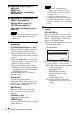
Connector Panel 3 1 72 46 Overview 3 5 Input (pages 8, 10) Others a INPUT A d LAN connector (page 29) Video: RGB/YPBPR input connector Audio: Audio input connector e AC IN (∼) socket Connects the supplied AC power cord. b INPUT B Video: HDMI input connector Audio: HDMI input connector c VIDEO Video: Video input connector Audio: Audio input connector f USB connector (Type A) ( (pages 11, 45) ) g USB connector (Type B) ( (page 43) ) Note The audio inputs of INPUT A and VIDEO are shared.
c Operating a menu (page 17) MENU key RESET key ENTER /V/v/B/b (arrow) keys RETURN key d Adjusting the image (page 13) ASPECT key (page 19) KEYSTONE key (page 15) PATTERN key (page 15) APA (Auto Pixel Alignment) key* (page 15) Note * Use this key when inputting a computer signal via the RGB input connector (INPUT A). e Using various functions during projecting D ZOOM (Digital Zoom) +/– key*1 Enlarges the image with the center of it as a starting point while projecting.
3 Select “User” then press the b key. The setting items appear. User Lamp Mode High Auto Power Saving Standby Mode :Sel Off Lamp Dimming Standard :Set RETURN Overview With No Input With Static Signal :Back 4 Press the V/v key to select the item then press the ENTER key. 5 Press the V/v key to select the setting value. 6 Press the ENTER key. The screen returns to the previous menu.
B Preparation Connecting the Projector Notes • Make sure all the equipment is powered off when connecting the projector. • Use the proper cables for each connection. • Insert the cable plugs firmly; Loose connections may reduce performance of picture signals or cause a malfunction. When pulling out a cable, be sure to grip it by the plug, not the cable itself. • For more information, refer also to the instruction manuals of the equipment you are connecting. • Use a no-resistance audio cable.
USB connector (Type B) ( ) For connecting to a computer with a USB connector (“Playing Video and Audio using USB Connection” (page 43)). USB connector (Type A) USB A-B cable (not supplied) Computer Preparation LAN connector For connecting to a computer, tablet PC, or smartphone via a hub or router (“Presentation Function via Network” (page 39)).
• When wirelessly connecting a tablet PC/smartphone to the projector via USB wireless LAN module IFU-WLM3 (supplied), set “Access Point Setup” to “Manual” in the projector’s “WLAN Settings” (page 25). Connecting a Video equipment Connections with a DVD player or BD player are explained for each input signal. VIDEO For connecting video equipment with a video output connector.
INPUT B For connecting video equipment with an HDMI output connector. HDMI cable (not supplied) HDMI output connector Video equipment Notes Preparation • Use HDMI-compatible equipment which has the HDMI Logo. • Use a high speed HDMI cable(s) on which the cable type logo is specified. (Sony products are recommended.) • The HDMI connector of this projector is not compatible with DSD (Direct Stream Digital) Signal or CEC (Consumer Electronics Control) Signal.
B Projecting/Adjusting an Image Projecting an Image The size of a projected image depends on the distance between the projector and screen. Install the projector so that the projected image fits the screen size. For details on projection distances and projected image sizes, see “Projection Distance” (page 61). 3 5 4 2 Video equipment Projector 1 6 Wall outlet Computer 1 Plug the AC power cord into the wall outlet. 2 Connect all equipment to the projector (page 8).
7 Adjust the focus, size and position of the projected image (page 13).
Adjusting the tilt of the projector with the foot adjust button/rear feet (adjustable) By changing the tilt of the projector with the foot adjust button/rear feet (adjustable), you can adjust the position of the projected image. 1 Press and hold the foot adjust button, then lift up the front of the projector to adjust the angle. 2 When the desired angle is achieved, release the foot adjust button to lock the position. 3 Set the angle of the projector precisely by turning the rear feet (adjustable).
Correcting trapezoidal distortion of the projected image (Keystone feature) Keystone feature may not work automatically when the screen is tilted. In this case, set keystone manually. 1 Press the KEYSTONE key on the remote commander or select V Keystone in the Installation menu. 2 Use the V/v/B/b the keys to set the value. The higher the value, the narrower the top of the projected image. The lower the value, the narrower the bottom.
Turning Off the Power 1 Press the ?/1 key on the unit or the remote commander. The projector starts shutdown and turns off. If you press the ?/1 key within 10 seconds of the message being displayed, shutdown is canceled. Note Do not turn off the projector soon after the lamp lights. It may cause a malfunction of the lamp (does not light ,etc.). 2 Unplug the AC power cord from the wall outlet.
B Adjustments and Settings Using a Menu Using a MENU Note The menu displays used for the explanation below may be different depending on the model you are using. 1 Press the MENU key to display the menu. 2 Select the setting menu. Use the V/v key to select the setting operations in step 3 and then press the ENTER key to register the setting. To return to the selection screen of the setting items, press the B or RETURN key.
The Picture Menu The Picture is used to adjust the picture for each input signal. Items Item descriptions Picture Mode Dynamic: Emphasizes the contrast to produce a dynamic and vivid picture. Standard: Provides an image which is natural and well balanced. Presentation*1: Provides a bright image, suitable for presentations. Blackboard: Provides an image suitable for displaying on a blackboard. Game: Provides an image suitable for viewing games. Cinema: Provides an image suitable for viewing movies.
The Screen Menu The Screen menu is used to adjust the size, position and aspect ratio of the projected image for each input signal. Items Item descriptions Changes the aspect ratio of the projected image (page 21). VPL-DX147/DX127: When the computer signal is input 4:3: Displays the image to fit the maximum projected image size with an aspect ratio fixed to 4:3. 16:9: Displays the image to fit the maximum projected image size with an aspect ratio fixed to 16:9.
Items Item descriptions Adjust Signal Adjusts the image of a computer signal. Use this item if the edge of the image is cut, or is not displayed properly. APA*2 *3 Automatically adjusts the projected image to an optimum quality when you press the ENTER key (page 6). Phase*2 Adjusts the dot phase of the display pixel and the input signal. Set to the value where looks clearest. Pitch*2 *5 The higher the value, the wider the horizontal image elements (pitch).
Aspect Input signal Recommended setting value and projected image 4:3 Full1*1 16:9 Full1*1 *2 16:10 Full1*1 *2 4:3 4:3*3 *1: If you select “Normal,” the image is projected in the same resolution as the input signal without changing the aspect ratio of the original image. *2: If you select “4:3,” the image is projected to fit the projected image size, regardless of the aspect ratio of the image. *3: Depending on the input signal, the projected image may be projected as illustrated below.
Video signal Computer signal VPL-DW127 Input signal Recommended setting value and projected image 4:3 Full1*1 *2 *3 16:9 Full1*1 *2 *3 16:10 Full1*3 4:3 4:3*4 *5 *1: If you select “Normal,” the image is projected in the same resolution as the input signal without changing the aspect ratio of the original image. *2: If you select “Full2,” the image is projected to fit the projected image size, regardless of the aspect ratio of the image.
The Function Menu The Function menu is used for setting various functions of the projector. Items Item descriptions Volume The higher the value, the louder an audio volume and the lower the value, the lower the audio volume. Smart APA On/Off: When set to “On,” APA functions automatically when a signal is input.*1 CC Display Off: Closed caption does not appear. CC1/CC2/CC3/CC4/Text1/Text2/Text3/Text4: Select the closed caption service (captions or text).
The Operation Menu The Operation menu is used for setting for the operations by using the menu or the remote commander. Items Item descriptions Language Selects the language used in the menu and messages. Status On: All on-screen statuses are enabled. Off: Turns off the on-screen displays, except for menus, warning messages and messages from the message list. Security Lock*1 On/Off: This function enables restriction of the projector to authorized users by password.
The Connection/Power Menu The Connection/Power menu is used for setting for the connections and power. Items Item descriptions LAN Settings IP Address Setup*9 Auto (DHCP): The IP address is assigned automatically from the DHCP server such as a router. Manual: To specify the IP Address manually. WLAN Settings*10 WLAN Connection*8 On/Off: Set the wireless output of the USB wireless LAN module (supplied) to On/Off. WLAN Network*13 Access Pt. (Auto)/Access Pt. (Manual)/Client *11: Changes modes for WLAN.
Items Item descriptions Direct Power On On/Off: When set to “On,” you can turn the power on without going to Standby mode when the AC power cord is connected to a wall outlet. With the projector turned off, you can also unplug the AC power cord without going to Standby mode, regardless of the Direct Power On setting. Notes *1: *2: *3: *4: *5: *6: *7: *8: *9: *10: *11: *12: *13: 26 This may not be optimum depending on the input signal. In this case, set manually according to the connected equipment.
The Installation Menu The Installation menu is used for installing the projector. Items Item descriptions Image Flip HV/H/V/Off: Flips the projected image horizontally or vertically according to the installation method. Installation Attitude Right Side Up/Upside Down/Link to Image Flip: Change the cooling setting to suit to the installation attitude. When set to “Link to Image Flip,” the cooling setting changes based on the setting of “Image Flip.
The Information Menu The Information menu is used to check projector status, such as total usage time of the lamp. Items Item descriptions Model Name Displays the model name. Serial No. Displays the serial number. fH/fV*1 Displays the horizontal/vertical frequency of the current input signal. Signal Type Displays the type of the current input signal. Lamp Timer Indicates the total usage time of a lamp. Note *1: These items may not be displayed depending on the input signal.
B Network Using Network Features Connection to the network allows you to operate the following features: • Checking the current status of the projector via a Web browser. • Remotely controlling the projector via a Web browser. • Receiving the e-mail report via the projector. • Making the network settings for the projector. • Displaying messages on the projected image using an application.
The following window appears in the Web browser: Entry area for [Administrator] Entry area for [User] Once you make the network settings, you can open the Control window only by performing step 3 of this procedure. How to operate the Control window Switching the page Click one of the Page Switching buttons to display the desired setting page. When you change the password, input a new password after deleting the password (*****) that was set.
Operating the Projector from a Computer 2 Set the timing of the e-mail report. Click on [Mail Report] to open the Mail Report page. Lamp Reminder (Lamp1): Set the timing of the email report for lamp replacement. To reset Lamp Reminder, execute “Lamp Timer Reset” on the projector (page 23). Maintenance Reminder: Set the timing of the email report for maintenance. To reset Maintenance Reminder, check the RESET check box and then click on [Apply].
Requires the use of POP Authentication before sending email (POP before SMTP): Check this check box to arrange for POP authentication to be performed before sending e-mail. Incoming Mail Server (POP3): Enter the address of the incoming-mail server (POP3) to be used for POP authentication. Account Name: Enter the mail account name. Password: Enter the password. SMTP Authentication: Check this check box to arrange for SMTP authentication to be performed before sending e-mail.
Speed: Select the network speed of the projector. Setting the WLAN Network of the projector Set the WLAN network function on the Setup page. Entered values will not be applied unless you click on [Apply]. 1 Click the [WLAN Setting] to open the WLAN Setting page. 2 3 (a) Input the settings for Access Pt. Mode. When the USB wireless LAN module is activated as an access point, set the items for the access point. Probe Response ON: Responds to the probe request from the client.
Encyption Type Open WEP 64bit WEP 128bit MIX (WPAPSK/WPA2PSK (TKIP/ AES)) or WPA2-PSK (AES) Password The password cannot be input. Input 5 ASCII characters for a password. Input 13 ASCII characters for a password. Input 8-63 ASCII characters for a password. Encyption Type Open WEP 64bit WEP 128bit MIX (WPAPSK/WPA2PSK (TKIP/ AES)) (b) Input the settings for Client Mode.
-Subnet Mask: Input the subnet mask of the projector. -Default Gateway: Input the default gateway of the projector. -Primary DNS: Input the primary DNS server of the projector. -Secondary DNS: Input the secondary DNS server of the projector. MAC Address: Displays the MAC address for USB wireless LAN module. 2 Click on the [Input Label] and open the Input label setting window. Clear the check box for the label that you want to change and input the label name.
Setting the Control Protocol of the Projector Change the settings for the control protocol on the Setup page. Entered values will not be applied unless you click on [Apply]. 1 Click on [Advanced Menu] to display the buttons for more settings. Advanced Menu button 2 -Community: Input the community name for Advertisement and PJ Talk. If the community name for Advertisement is changed, the one for PJ Talk will also be changed. Only four alphanumeric characters can be input.
(c)Set PJ Link. PJ Link Service setting area PJ Link button Start PJ Link Service: Set PJ Link to enabled or disabled. Items for PJ Link are enabled only when this function is enabled. This function is disabled at the factory setting. -Requires Authentication: Set the authentication for PJ Link to enabled or disabled. -Password: Input the authentication password for PJ Link. For the factory default password, refer to the PJ Link specifications. (d)Set the system service.
(e)Reset the network settings. Reset button Reset Reset: Reset all Web browser settings to their factory defaults.
B Presentation Function via Network Using Presentation Function via Network The Presentation Function via Network enables you to do the following: • Connect a maximum of eight computers to the projector. • Project images from a maximum of four computers simultaneously. • Connecting a USB wireless LAN module (not supplied) to the projector as an access point, allows the projector to connect to up to seven computers simultaneously.
3 Start Projector Station for Network Presentation. For Windows: Select [Start]-[All Programs]-[Projector Station for Network Presentation] on the computer. For Mac: Double-click [Projector Station for Network Presentation] in Applications folder. Projecting an Image After starting Projector Station for Network Presentation, the connection setting window appears. 1 Find projectors connected to the network. Click “Search” in the connection setting window to search for projectors.
Item SSID IP Address Search Delete Property Connect Manual Connect Item descriptions Displays the strength of the wireless signal (appears only when wireless connection is used). Display SSID (appears only when wireless connection is used). Display IP address (appears only when wired connection is used). Start searching for projectors in the network. Delete selected profile. Display the properties of the selected profile. Connect to the selected projector and start projecting an image.
*1: To use the application, one of the following conditions is required. • Connected to network where wireless connection can be established (page 9). • Connected to a wireless network via USB wireless LAN module IFU-WLM3 (not supplied) that is connected to the projector (page 9). *2: Depending on your Internet connection, a data communication fee may apply.
B Playing Video and Audio using USB Connection Playing Video and Audio using USB Connection OS Windows XP: Home/Professional (recommended) Windows Vista: Home Premium/Business/Ultimate/Enterprise Windows 7: Home Premium/Professional (Recommended)/Ultimate/Enterprise Windows 8 Mac OS X: 10.6.x/10.7.x/10.8.x CPU Pentium4 2.8GHz or faster Starting USB Display 1 Connecting the projector and your computer with a USB A-B cable (not supplied) (page 9). 2 Turn on the projector.
For Mac: Items Functions Start audio/video playback. Pause audio/video playback. Stop audio/video playback (the screen turns black). Display information about USB Display.
B USB Media Viewer Using USB Media Viewer You can browse image files stored in a USB memory device inserted in the USB connector of the projector, without using a computer. Supported storage media and file format: • Supported storage media: USB flash memory • Supported format of storage media: FAT format • Supported file format: JPEG (.jpg/.jpeg), Bitmap (.bmp), PNG (.png), GIF (.gif), TIFF (.tif/.tiff) Notes 1 Connect a USB Memory device to the projector (page 11).
Thumbnail Mode The image files in the folder are displayed as a thumbnail list. Option menu Press the V/v/B/b key on the remote commander to select an image, then press the ENTER key. The option menu appears in the lower part of the screen. Option Menu You can select the display order of thumbnails and display method of image files. Items Item descriptions Hide the option menu. Switch to the display mode, and display the selected image in full screen view.
Display Mode In display mode, you can view a selected image in full screen view. Press the ENTER key on the remote commander. The option menu appears in the lower part of the screen. USB Media Viewer Option menu Option Menu Items Item descriptions Hide the option menu. Return to the thumbnail mode (page 46). Rotate the image 90 degrees counter-clockwise. Rotate the image 90 degrees clockwise. Switch to the slideshow mode, and start the slideshow from the selected image.
Option Menu Items Item descriptions Hide the option menu. Return to the thumbnail mode (page 46). Display the previous image. Display the next image. Press the V/v key to change the slideshow time interval. 3 Slideshow time interval 3 After 3 seconds, display the next image. 5 After 5 seconds, display the next image. 10 After 10 seconds, display the next image. Press the V/v key to change the slideshow effect. Slideshow effect The next image appears with tile transition effect.
B Others Indicators The indicators allow checking the status and notify you of abnormal operation of the projector. If the projector exhibits abnormal status, address the problem in accordance with the table below. ON/STANDBY indicator Status Meaning/Remedies Lights in red The projector is in Standby mode. Flashes in green • The projector is ready to operate after having been turned on. • The lamp cools after the projector is turned off. The projector’s power is on.
Messages List When any of the messages listed below appears on the projected image, address the problem in accordance with the table below. Messages Meaning/Remedy High temp.! Lamp off in Check the items below. 1 min. • Check if nothing is blocking the ventilation holes. • Check if the air filter is not clogged. • Check if the Installation Attitude in the Installation menu is set correctly.
Troubleshooting Before asking to have the projector repaired, try to diagnose the problem, following the instructions below. Remedy The power is not turned on. Check if the AC power cord is firmly connected. – When the “Control Key Lock” is set to “On,” you cannot turn on the projector using the ?/1 key on the projector. 24 If the lamp or lamp cover is not attached securely, the projector cannot be turned on. 53 Check if the connecting cable is connected to external equipment firmly.
Symptoms Remedy Page The image is dark/too bright. The settings for “Brightness,” “Contrast,” and “Lamp Mode” affect brightness of the image. Check if the value is appropriate. 18, 25 The image will be dark when the lamp is burnt out. Check “Lamp Timer,” and replace the lamp with a new one if necessary. 28, 53 The image becomes darker or brighter. The image is not clear. “With Static Signal” is set to “On.” 25 During picture muting, the lamp is dimmed to reduce power consumption.
Replacing the Lamp Replace the lamp with a new one if a message displayed on the projected image (page 50). Use an LMP-D213 projector lamp (not supplied) for replacement. Caution 1 Turn off the projector, and disconnect the AC power cord from a wall outlet. 2 When the lamp has cooled sufficiently, open the lamp cover by loosening one screw. Others • The lamp remains hot after the projector is turned off. If you touch the lamp, you may burn your finger.
Caution Do not put your hands into the lamp replacement slot, and do not allow any liquid or other objects into the slot to avoid electrical shock or fire. 4 Insert the new lamp all the way in until it is securely in place (1). Tighten the two screws (2). Fold down the handle to replace it (3). 6 Connect the AC power cord to a wall outlet and turn on the projector. 7 Reset the lamp timer for notification of the next replacement time.
Cleaning the Air Filter When a message appears on the projected image indicating time for a filter cleaning, clean the air filter (page 50). If the dust cannot be removed from the air filter even after cleaning, replace the air filter with a new one. For details on purchasing/fitting a new air filter, consult with the store where you purchased the projector, or contact qualified Sony personnel. Caution If you neglect to clean the air filter, dust may accumulate, clogging it.
Specifications Items Descriptions Model VPL-DX147/DX127/VPL-DW127 Projection system Display device Projection lens 3 LCD system Effective display size VPL-DX147/DX127: 0.63 inch (16.0 mm), 3 plate panels, Aspect ratio 4:3 VPL-DW127: 0.59 inch (15.0 mm), 3 plate panels, Aspect ratio 16:10 Effective picture elements VPL-DX147/DX127: 2,359,296 pixels (1024 × 768 pixels, 3 plate panels) VPL-DW127: 3,072,000 pixels (1280 × 800 pixels, 3 plate panels) Zoom Manual zoom: VPL-DX147/DW127: approx.1.
Items Descriptions Model INPUT OUTPUT (Computer/video) Other connectors VPL-DX147/DX127/VPL-DW127 INPUT A RGB/YPBPR input connector: Mini D-sub 15 pin female, G with sync/Y: 1 Vp-p ± 2 dB, sync negative, 75 ohms terminated, RGB/PBPR: 0.
Items Descriptions Model VPL-DX147/DX127/VPL-DW127 Heat dissipation VPL-DX147: 100V to 120V AC: 1,014BTU 220V to 240V AC: 973BTU VPL-DX127: 100V to 120V AC: 1,011BTU 220V to 240V AC: 970BTU VPL-DW127: 100V to 120V AC: 1,024BTU 220V to 240V AC: 977BTU Standard dimensions (W/H/D) Approx. 315 × 87.2 × 233 mm (12 13/32 × 3 7/16 × 9 3/16 inches) Approx. 315 × 75 × 230.5 mm (12 13/32 × 2 15/16 × 9 1/16 inches) (without projecting parts) Mass Approx. 2.6 kg (5.
Pin assignment HDMI connector (HDMI, female) 19 1 18 RGB input connector (Mini D-sub 15-pin, female) 2 T.M.D.S. Data2+ 11 T.M.D.S. Clock Shield 2 T.M.D.S. Data2 Shield 12 T.M.D.S. Clock – 3 T.M.D.S. Data2 – 13 N.C. 4 T.M.D.S. Data1+ 14 RESERVED (N.C.) 5 T.M.D.S. Data1 Shield 15 SCL 6 T.M.D.S. Data1 – 16 SDA 7 T.M.D.S. Data0+ 17 DDC GND 8 T.M.D.S. Data0 Shield 18 +5V Power 9 T.M.D.S. Data0 – 19 Hot Plug Detect 10 T.M.D.S.
Acceptable Input Signals*1 Resolution Computer signal Resolution fH[kHz]/ 640 × 350 fV[Hz] RGB/ YPBPR 31.5/70 z 37.9/85 z 31.5/70 z 37.9/85 z 31.5/60 z 35.0/67 HDMI 1280 × 800 Input connector fV[Hz] RGB/ YPBPR HDMI 49.7/60 z z Digital TV signal*4 Input connector Signal fV[Hz] RGB/ YPBPR HDMI 480i 60 z z 576i 50 z z z 480p 60 z z 37.9/73 z 576p 50 z z 37.5/75 z 1080i 60 z z 43.3/85 z 1080i 50 z z 35.2/56 z 720p 60 z z 37.
Projection Distance The projection distance is the distance between the front of the lens and the surface of the projected image. The following describes the projection distance and height from the center of the lens to edge of screen by each projected screen size. Height H is the height from the bottom of the projected image (top for ceiling mount) to A (determined by drawing a perpendicular line from the center of the lens to projected image surface).
Ceiling Installation Height H from center of lens to edge of screen Center of lens A Top side Projected image Projection distance L L: Projection distance L H: Height H from center of lens to edge of screen 62 Projection Distance
Projection distance table (VPL-DX147) Unit: m (inches) Height H from center of lens to edge of screen Projected image size Projection Distance L Width × Height 80 inch (2.03 m) 1.63 × 1.22 (64 × 48) 2.03 × 1.52 (80 × 60) 2.44 × 1.83 (96 × 72) 3.05 × 2.29 (120 × 90) 4.06 × 3.05 (160 × 120) 100 inch (2.54 m) 120 inch (3.05 m) 150 inch (3.81 m) 200 inch (5.08 m) 2.25-2.92 (89-115) Minimum Projection Distance L -0.20 (-8) Maximum Projection Distance L -0.20 (-8) 2.81-3.66 (111-144) -0.25 (-10) -0.
Projection distance table (VPL-DX127) Unit: m (inches) Height H from center of lens to edge of screen Projected image size Projection Distance L Diagonal D Width × Height 80 inch (2.03 m) 1.63 × 1.22 (64 × 48) 2.03 × 1.52 (80 × 60) 2.44 × 1.83 (96 × 72) 3.05 × 2.29 (120 × 90) 4.06 × 3.05 (160 × 120) 100 inch (2.54 m) 120 inch (3.05 m) 150 inch (3.81 m) 200 inch (5.08 m) 2.42-2.88 (95-113) Minimum Projection Distance L -0.20 (-8) Maximum Projection Distance L -0.20 (-8) 3.02-3.60 (119-141) -0.
Projection distance table (VPL-DW127) Unit: m (inches) Height H from center of lens to edge of screen Projected image size Projection Distance L Width × Height 80 inch (2.03 m) 1.72 × 1.08 (68 × 42) 2.15 × 1.35 (85 × 53) 2.58 × 1.62 (102 × 64) 3.23 × 2.02 (127 × 79) 4.31 × 2.69 (170 × 106) 100 inch (2.54 m) 120 inch (3.05 m) 150 inch (3.81 m) 200 inch (5.08 m) 2.36-3.05 (93-120) Minimum Projection Distance L -0.20 (-8) Maximum Projection Distance L -0.20 (-8) 2.95-3.82 (117-150) -0.25 (-10) -0.
Dimensions 2.5 (3/32) 7.5 ± 1 (9/32) 315 (12 13/32) 11.9 ± 1 (15/32) 230.5 (9 1/16) Top VPL-DX147/VPL-DW127 Edge of lens VPL-DX127 Edge of lens Unit: mm (inches) Front 46.3 (1 26 (1 1/32) 66 (2 19/32) 78 (3 1/16) 87.2 (3 7/16) 75 (2 15/16) 33.3 (1 5/16) 81 (3 3/16) 13/16) 157.
Side 69 (2 23/32) 113 (4 7/16) 69 (2 23/32) 31 (1 7/32) Unit: mm (inches) 164.4 (6 15/32) 157.5 (6 3/16) 48 (1 7/8) 16.8 (21/32) Others Rear 28 (1 3/32) 252.
Bottom 23.9 (15/16) 99.9 (3 15/16) 88.5 (3 15/32) 271 (10 21/32) 207.5 (8 5/32) 79.4 (3 1/8) 76.4 (3) 105.8 (4 5/32) 38.8 (1 17/32) 83.5 (3 9/32) 78.
END USER LICENSE AGREEMENT IMPORTANT: BEFORE USING THE SOFTWARE, PLEASE READ THIS END USER LICENSE AGREEMENT (“EULA”) CAREFULLY. BY USING THE SOFTWARE YOU ARE ACCEPTING THE TERMS OF THIS EULA. IF YOU DO NOT ACCEPT THE TERMS OF THIS EULA, YOU MAY NOT USE THE SOFTWARE.
EXCLUDED SOFTWARE AND OPEN SOURCE COMPONENTS Notwithstanding the foregoing limited license grant, you acknowledge that the SOFTWARE may include EXCLUDED SOFTWARE.
EXPORT AND OTHER REGULATIONS You agree to comply with all applicable export and re-export restrictions and regulations of the area or country in which you reside, and not to transfer, or authorize the transfer, of the SOFTWARE to a prohibited country or otherwise in violation of any such restrictions or regulations. EXCLUSION OF WARRANTY ON SOFTWARE You acknowledge and agree that use of the SOFTWARE is at your sole risk and that you are responsible for use of the SOFTWARE.
LEGAL THEORY RELATED TO THE SOFTWARE, INCLUDING, BUT NOT LIMITED TO, ANY DAMAGES ARISING OUT OF LOSS OF PROFITS, LOSS OF REVENUE, LOSS OF DATA, LOSS OF USE OF THE SOFTWARE OR ANY ASSOCIATED HARDWARE, DOWN TIME AND USER’S TIME, EVEN IF ANY OF THEM HAVE BEEN ADVISED OF THE POSSIBILITY OF SUCH DAMAGES. IN ANY CASE, EACH AND ALL OF THEIR AGGREGATE LIABILITY UNDER ANY PROVISION OF THIS EULA SHALL BE LIMITED TO THE AMOUNT ACTUALLY PAID FOR THE PRODUCT.
countries may not offer the same level of protection as your country of residence and you may have fewer legal rights in relation to Information processed and stored in, or transferred to, such countries. SONY will use reasonable efforts to take appropriate technical and organizational steps to prevent unauthorized access to or disclosure of Information, but does not warrant it will eliminate all risk of misuse of such Information.
PROCESS IN WHICH YOU OBTAIN UPGRADES/UPDATES OR BY ANY OTHER LEGALLY RECOGNIZABLE FORM OF NOTICE. If you do not agree to the amendment, you should promptly contact SONY for instructions. Your continued use of the SOFTWARE after the effective date of any such notice shall be deemed your agreement to be bound by such amendment.
Index A AC IN ........................................................5 Acceptable input signal ...........................60 Adjust Signal ...........................................20 Air filter ...................................................55 Air filter cover/Ventilation holes (intake) ...............................................4 APA ...........................................................6 Aspect ............................................6, 19, 21 Audio muting .............................
R About Trademarks Rear feet (adjustable) .......................... 4, 14 Remote commander .................................. 5 Remote control detector ............................ 4 Replacing the lamp ................................. 53 Reset ........................................................ 18 • Adobe and Adobe Acrobat are trademarks or registered trademarks of Adobe Systems Incorporated in the United States and/or other countries.
Sony Corporation