
Operating Instructions
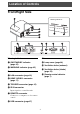
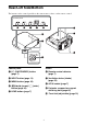
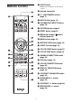
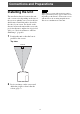
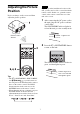
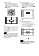
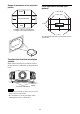
Table Of Contents
- Table of Contents
- Location of Controls
- Connections and Preparations
- Projecting
- Using the Menus
- Using Network Features
- Error Handling
- Others

3
Front/Right Side
Warning indicators
a ON/STANDBY indicator
(page 45)
b WARNING indicator (page 45)
Connectors
c LAN connector (page 39)
d HDMI 1/HDMI 2 connector
(page 11)
e TRIGGER connector (page 35)
f IR IN connector
Inputs signals to control the unit.
g REMOTE connector
Connects to a computer, etc. for remote
control.
h USB connector (page 47)
Others
i Lamp cover (page 48)
j Ventilation holes (exhaust)
k Ventilation holes (intake)
(page 50)
l Remote control detector
(page 7)
Location of Controls
Warning indicators