3-243-056-22(1) Media Center/ Receiver Installation/Connections GB 安裝 CT 連接 Notice to dealers and installers Please return this manual to the customer after the installation is completed.
Precautions Unit is designed for negative ground 12 V DC systems only The unit cannot be used in trucks or other cars with 24 V systems. Otherwise, there is a risk of fire and damage. Do not disassemble or remodel the unit This can cause electric shock, personal injury or fire. Do not connect any other system’s power supply cord to this unit’s power supply cord directly. If you are in any doubt about the safe installation of this unit, please consult your nearest Sony dealer.
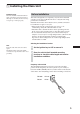
Table of Contents Precautions .................................................................................................................... 2 Parts List ........................................................................................................................ 4 1 Installing the Main Unit .......................................................................................... 5 Before installation .........................................................................................
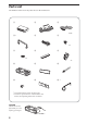
Parts List The numbers in the list are keyed to those in the instructions. 1 2 3 5 6 2.5 m 4 *1 ×4 7 8 9 ×2 ×2 q; qa qs qd qf qg *1 Packed while being fixed to the main unit. *2 Use this to replace the fuse or dismount the unit. Refer to the Operating Instructions for details. CAUTION Handle the bracket q; carefully to avoid injuring your fingers.
1 Installing the Main Unit Installation angle The unit should be installed within an angle of 25 degrees from horizontal. If this angle is exceeded, the monitor may not open up or retract properly. Before installation This unit is designed to be completely safe, but if not installed correctly, it can cause accidents. Be sure to verify the following points before installation. Install the main unit to the in-dash location, and the connection box under the navigator’s seat, etc.
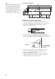
Cluster panel dimensions 175.4 22.5 6.2 171 Center line 25 25.5 If the installation dimensions shown at right are not observed, the monitor may not open up smoothly. If this happens, check the installation once more and modify the cluster panel where the dimension requirements are not met. For some car models, a separately available mounting kit may be required. (For details, please consult your dealer.) 17.3 Note 18 33.6 44.7 55.7 20.
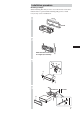
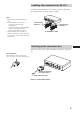
Installation procedure Mounting example When installing this unit, be sure to close the monitor of the unit. If the monitor is opened while installing and given too much force, it may cause a malfunction. 182 1 mm 53 mm q; 2 Bend these claws outward for a tight fit, if necessary.
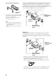
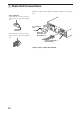
When removing front panel plate Toyota cars (illustration shows an example for a Toyota car) Align the brackets of the factory-installed car stereo with the mounting holes marked “T” on the side of the Media Center main unit, and use the supplied screws to fasten the brackets. For Toyota cars, the supplied screws 6 should be used.
Installing the connection box XA-114 Cut off the required length of hook-and-loop fastener 8 and fix the connection box 1 on the carpet or similar. Note • Ensure that the mounting surface is clean. • Do not install the connection box - in locations subject to high temperatures - in locations subject to direct sunlight, warm air from heater outlets, or other locations that can get hot.
2 Main Unit Connections Refer also to the section “3 Car Systems Connections” (page 14 15). Use of connectors Insert until the connector clicks into place. To remove, press here and pull out. To connection box Insert until the connector clicks into place. To remove, press here and pull out. Main unit/ connection box interconnect 3 Power supply leads 2 (for main unit) Insert 2 and 3 until a click is heard.
Connection Example For details, see the section “3 Car Systems Connections” (page 14 - 15). Be sure to refer also to the documentation for all other components in the system.
Connection of separately available accessories Items except the main unit and the connection box are optionally available.
Connecting Information For details, see the section “3 Car Systems Connections” (next page). Using the tap Attach and fix the tap securely as illustrated. Notes • Be sure to connect the power input cord after all other cords have been connected. • If the parking brake switch cord is too thin, connect the parking cord to the parking brake switch cord directly without using the tap.
3 Car Systems Connections Refer also to the documentation for all other components in the system. Also see “Connecting Information” on page 13. • Components listed here except for supplied accessories are available separately. When connecting such components, be sure to also refer to their documentation. For specifications and other information on separately available components, contact your dealer.
RCA interconnects (optional) Bus cable (5.3 m) (supplied with XT-63V) RCA interconnects (5.
4 After Installation and Connections 1 Start the car’s engine. that the brake lights, other lights, horn, turn 2 Verify indicators, and all other electrical parts operate normally. Note To avoid the possibility of damage, you should not use a needle or push the button too strongly. a ball-point pen or similar to push the Reset 3 Use button on the unit. Reset button When you press the Reset button, the system becomes operative.
Removing the Front Panel Plate To remove the front panel plate from the unit, use the following procedure. Insert a coin and twist to remove the front panel plate. Be careful not to pull off the plastic parts. Front panel plate Plaque de panneau avant A B the lower side of the front 1 Pull panel plate forward (arrow A), to open a gap between the front panel plate and the body of the unit. a coin or similar thin item in 2 Insert this gap, and twist to remove the front panel plate.
操作前注意事項 本機僅用於負極接地的12V直流系統 本機不能用於使用2 4 V 系統的卡車或其他汽車 上。否則,可能會導致火災和損壞。 不要拆卸或改裝本機 這可以引起觸電、人身傷害或火災。不要把其他 系統的電源線和本機電源線直接相連。如果對本機的 安全安裝有疑問,請向最近的Sony經銷商咨詢。 不要在妨礙安全氣囊操作的地方安裝本機 否則,可能會引發事故和人身傷害。 只使用指定的保險絲 更換保險絲時,請務必使用相同規格的保險絲 (電流規格)。否則,可能引起火災。 不要阻塞通風 如果本機放在地毯、地板墊或其他覆蓋物之下, 通風孔和散熱片將不能對本機進行充分冷卻,從而導 致本機過熱,並有發生火災或嚴重事故的危險。 注意 • 不要把電線壓在螺釘下面或夾在移動部件(例如座 位扶手)中。 • 在連接前,請把點火鑰匙轉到off以避免短路。 • 只有連接其他所有導線後,才能連接黃色和紅色電 源輸入導線。 • 把所有地線連到一公共的接地點。 • 為了安全,務必用電工膠帶絕緣任何未連接的電 線。 電源線(黃色)注意事項 • 當本機和其他立體聲部件相連時,連接的汽車電路 額定電流必須大於每一部件保險絲額定電流的總 和。
目錄 操作前注意事項 ............................................................. 2 部件列表 ................................................................... 4 1 安裝主機 ............................................................... 5 安裝之前 ................................................................ 5 安裝過程 ................................................................ 7 安裝連接盒XA-114 ........................................................ 9 連接連接盒 ..............................................................
部件列表 列表中的號碼和說明書中的號碼相對應。 1 2 3 5 6 2.
1 安裝主機 安裝角度 本機的安裝角度應為水平25度之內。如果超 過這一角度,監視器可能不能正常打開或 收回。 安裝之前 本機的設計是十分安全的,但如果安裝不正確,可能引起事故。 在安裝前請務必確認下列各點。 把主機安裝到儀表板上。並把連接盒安裝到副駕駛座等下面。 • 如果打開的監視器靠近空調出風口,應關閉出風口。 • 監視器打開時不應妨礙危急開關或其他重要控制部件的使用。 • 不要把本機(監視器)安裝在要經受高溫或低溫的位置(否則,外 殼可能變形,液晶顯示屏可能損壞。) 受到陽光直射也會導致高溫,應該加以避免。 選擇安裝位置 注意 把設備和連接電纜分開。 媒介中心主機和連接盒 1 不要靠得太近。 1 把點火鑰匙設為OFF或取下。 2 把設備放入計劃好的安裝位置,檢查電纜長度和監視器安 裝條件。 頻率選擇開關 AM(FM)調諧間隔工廠預設為9k(50k)位置。如果您所在國家的頻 率分配系統是基於10kHz(200kHz)間隔的,在連接前請把本機底部的 開關設到10k(200k)位置。 FM 200k AM 10k FM 50k AM 9k 5
組件面板尺寸 如果不按照右圖所示的安裝尺寸安裝,監視 器可能不能順利打開。此時,請再次檢查安 裝,修改不滿足尺寸要求的組件面板,對於 某些車型,可能需要另購的安裝套件。 (詳情請向經銷商咨詢。) 175.4 25 25.5 中心線 17.3 6.2 171 22.5 注意 18 33.6 44.7 55.7 20.
安裝過程 安裝示例 當安裝本機時,務必關閉本機的監視器。 在安裝時如果監視器打開且用力過度,可能發生故障。 1 182 mm 53 mm q; 2 如果需要,請朝外彎曲這些 爪卡以實現緊配合。 3 7 6 6 9 9 9 4 6 儀表板 防火壁 q; qa qs qd 7
當取下前面板板時 豐田汽車(插圖顯示的是豐田汽車的連接示例) 把工廠安裝的汽車立體聲機架和媒介中心主機側面標有“T” 的安裝孔對準,使用附帶的螺釘安裝機架。對於豐田汽車,請使用 附帶的螺釘 6。 6 XAV-7W 前面板板 4 工廠安裝的汽車立 體聲機架 不要丟棄前面板板,因為當安裝本機的汽 車改變時,它會有用。 詳情請參見“取下前面板板”。(第17 頁) 。 CSX-V58MP (選購) 注意 • 安裝期間不要按本機前面板上的按鈕,不 要用強力。 • 不要在本機頂上放任何物體。 工廠安裝的汽車立 體聲機架螺釘 尼桑汽車 把工廠安裝的汽車立體聲機架和媒介中心主機側面標有“N” 的安裝孔對準,使用附帶的盤頭螺釘 6 安裝機架。 6 XAV-7W 工廠安裝的汽車 立體聲機架 CSX-V58MP (選購) 工廠安裝的汽車立 體聲機架螺釘 * 務必只使用附帶的盤頭螺釘 6 進行安裝。如果使用其他螺釘, 請確保它們符合下圖的要求,使用較長的螺釘可能使本機內部受 損。 5 mm 6 mm 如果螺釘直接裝在本機上而不使用工廠安裝的汽車立體聲機 架,也可能造成損壞。 8
安裝連接盒XA-114 剪下所需長度的粘扣帶 8,並把連接盒 1 安裝在地毯或類似 物體上。 注意 • 確保安裝表面是清潔的。 • 不要在高溫處 - 陽光直射位置 - 受加熱器出口熱空氣侵襲或其他受熱位 置安裝連接盒。 • 當把粘扣帶粘到連接盒底部時,請不要覆 蓋中央的型號銘牌。 粘扣帶 8 粘扣帶 8 在安裝表面上 連接連接盒 也請參見“3 汽車系統連接”(第14-15頁)。 使用連接器 插入直到連接器喀嗒一聲到位。要取出, 按此處並拉出。 主機 連接盒互連器 3 到媒介中心主機 插入 3 直到聽到喀嗒聲。 9
2 主機連接 也請參考“3 汽車系統連接”(第14-15頁)。 使用連接器 插入直到連接器喀嗒一聲到位。要取出,請 按此處並拉出。 到連接盒 主機 連接盒互 連器 3 插入直到連接器喀嗒一聲到位。要取出,請 按此處並拉出。 電源線 2(用於主機) 插入 2 和 3 直到聽到喀嗒聲。 10
連接示例 詳情參見“3 汽車系統連接”(第14-15頁)。務必也請參考系統中所有其他組件的說明書。 揚聲器連接 前揚聲器(選購) 媒介中心主機 SUB WOOFER OUT(MONO) 後揚聲器(選購) 有源超低音揚聲器 (選購) 前揚聲器(選購) FRONT AUDIO OUT 媒介中心主機 放大器(選購) SUB WOOFER OUT(MONO) REAR AUDIO OUT 後揚聲器(選購) 有源超低音揚聲器(選購) 注意 • 連接放大器前,務必先連接地線。 • 如果連接一選購的電源放大器而不使用內置放大器,將不發出嗶聲。 11
連接另購的附件 除主機和連接盒以外的各項是選購件。 帶Sony總線系統電視調諧器XT-63V(NTSC 制式) CONTROL(IN) CONTROL(OUT) 電視調諧器 INPUT OUTPUT CD/MD換碟機,或設備源 選擇器XA-C30 VIDEO IN 監視器 CONTROL INPUT REAR MONITOR OUTPUT 連接盒(附帶) 媒介中心主機 INPUT1/2 XAV 視訊組件 不帶電視調諧器 CONTROL(OUT) 系統上VCD/MP3播放機 CSX-V58MP,CD/MD換 碟機或設備源選擇器 CONTROL(IN) XA-C30 CD/MD換碟機 INPUT OUTPUT CONTROL VIDEO IN 監視器 INPUT REAR MONITOR OUTPUT 連接盒(附帶) 媒介中心主機 XAV INPUT1/2 視訊組件 要點 要連接兩個或多個CD/MD換碟機,需要設備源選擇器XA-C30(選購)。 12 CD/MD換碟機
連接資訊 詳情參見“3 汽車系統連接”(下一頁)。 使用分接頭 如圖所示牢固地連接並固定分接頭。 注意 • 務必在所有其他電線已連接後再連接電源 輸入線。 • 如果剎車開關導線太細,則不要使用分接 頭,直接把停車線連到剎車開關導線。 剎車開關導線 分接頭 5 停車線(淺綠色) 連接停車線 務必把停車線(淺綠色)連到剎車開關導線上,剎車開關導線的 固定位置和您的汽車有關。進一步的詳情請參見下面的系統連接圖並 向汽車經銷商或最近的Sony經銷商咨詢。 電池電源 剎車警告燈 剎車開關導線 分接頭 5 停車線(淺綠色) 媒介中心主機 剎車開關 車身接地 剎車開關導線 腳剎型 手剎型 剎車開關導線 13
3 汽車系統連接 也請參見系統中所有其他組件的說明書。 也請參見第13頁的“連接資訊”。 • 除了隨機附件外,這裡所列的組件需要另購。當連接此類組件時,務必也請參見它們的說明書。 有關另購組件的規格和其他資訊,請和經銷商聯繫。 防止短路引起事故 為了防止短路引起事故,只有在其他線路連接完後才能連接電源線(紅色和黃色),且點火鑰匙必須在 OFF位置。 否則,意外的短路可能引起觸電和嚴重的損壞。 當保險絲熔化時,在更換保險絲之前請先檢查線路並確定問題原因。當更換保險絲時,請務必使用相同 規格的保險絲(電流規格)。使用不同的保險絲或用電線連接是非常危險的,可能引起嚴重的損壞。 務必連接下列所有導線。 否則,可能導致觸電、設備損壞或故障。 • 連接淺綠色導線到汽車的剎車開關導線。 • 連接黃色導線到汽車的電池電源。 • 連接紅色導線到汽車的輔助電源。 • 連接黑色導線到汽車底盤的金屬點上。 * 不要混淆黃色和紅色導線,這將引起記憶體內容丟失。 請遵守下列事先注意事項。 否則,可能引起觸電、設備損壞或故障。 • 用電工膠帶纏好不用的連接器以防意外接觸。 • 使FM/AM天線電纜、總線電纜、RCA互連器和電源線相互之間盡
RCA互連器(選購) 總線電纜 (5.3m)(XT-63V附帶) RCA互連器 (5.3m) (XT-63V附帶) 前揚聲器(選購) 放大器 (選購) RCA互連器(選購) CONTROL 後揚聲器(選購) INPUT 連接盒1 RCA互連器(選購) 電視調諧器 XT-63V(選購) XAV 有源超低音揚聲器 (選購) 左 前揚聲器(選購) 右 左 主機 連接盒互 連器 3 旋轉主控器RM-X4S (選購) 白色 白色 黑色 灰色 灰色 黑色 綠色 綠色 黑色 媒介中心主機 後揚聲器(選購) 右 紫色 從汽車天線 紫色 黑色 黑色 (0.45m) 到汽車的金屬表面 *2 黃色 (0.25m) 保險絲(10A) 到+12V電源端子,它隨時供電 *1 電源線 2 (用於主機) 紅色 (0.25m) 到+12V電源端子,它在點火鑰匙開關 * 1* 3 的輔助位置供電 橙色 白色 (0.25m) 到汽車的照明信號 *1 淺藍色 (0.
4 安裝和連接以後 1 啟動汽車引擎。 2 確認剎車燈、其他燈、喇叭、轉向指示燈和所有其他電氣 部件工作正常。 注意 為防止損壞,不應使用針或過度用力按按 鈕。 3 使用圓珠筆或類似物體按本機的重設按鈕。 重設按鈕 當按下重設按鈕時,系統可以操作。 當在點火鑰匙開關沒有ACC(輔助)位置的汽車上安裝時的警 告 在關閉引擎後務必按住本機上的OFF按鈕2秒以上以關閉時鐘顯 示。 當只是瞬間按下OFF按鈕時,時鐘顯示不關閉並會引起電池損 耗。 16
取下前面板板 要從本機上取下前面板板,執行下列步驟。 插入一個硬幣並扭轉,取下前面板 板。 當心不要扯下塑料部件。 A B 前面板板 向前拉前面板板的底邊(箭頭 A),使 1 前面板板和本機機體之間露出一條縫。 2 在此縫中插入一個硬幣或類似的薄物 體,並扭轉以取下前面板板。 當心不要損壞本機。 按從左到右的順序取下。 3 向外側拉伸前面板板的底邊(箭頭 B),把板從機體上卸下。 注意 當心不要把本機底面上的塑料部件和前面板板一起拉下。 17
18
19
Sony Corporation Printed in Japan Printed on recycled paper