
Instruction Manual


4/8
Form 416 (01.13) ©SOR Inc.
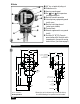
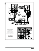
Dimensions
3/4” hex set point adjusting nut
Calibration scale
Housing mounting pad
See
g
and for temperature
sensing probe details
Electrical conduit connection
Internal primary equipment ground
(earth) screw
Electrical switching element
(under terminal block)
Terminal block
External supplemental case ground
(earth)
Vent hole 1/4” NPT(F) (Prevents
pressurization of the electrical switch
compartment in the event of sensing
element failure.)
(See Caution on page 2.)
B-Series
Linear = mm/inches
Drawing 0190130
Dimensions are for reference only. Contact the factory
for certified drawings for a particular model number.
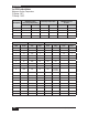
40.8
1.61
33.4
1.32
26.6
1.05
9.5
0.38
35.3
1.39
110.3
4.34
C
147.4
5.80
188.6
7.42
252.5
9.94
40.0
1.58
80.0
3.15
75.1
2.95
150.1
5.91
E
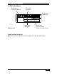
2X
MOUNTING
HOLES
9.1
0.36
ELECTRICAL CONNECTION
(LH & RH)
B3 & B6: 3/4 NPTF (STD)
1/2 NPTF (OPT)
B4 & B5: M20 X 1.5
J4: 3/4 PFF RH ONLY
1/4 NPTF (LH & RH)
VENT CONNECTION
28.7
1.13
WRENCH FLATS
OR HEX
PROCESS
CONNECTION
1/2 NPTM
TEMPERATURE
SENSING BULB