
Owner manual

Form 1296 (05.13) ©SOR Inc.
1/4
These instructions cover installation, process connection, electrical connection
and calibration of the SOR
®
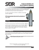
Pressure Switches for Fire Protective Signaling
with Hermetically Sealed Electrical Switching Elements
.
The static-o-ring type Pressure Switch is suitable for a wide variety
of process applications.
Pressure Switches for
Fire Protective Signaling
General Instructions
Registered Quality System to ISO 9001
NOTE: If you suspect that a product is defective, contact the factory
or the SOR Representative in your area for a return authorization
number (RMA).
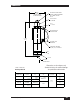
Installation
This product should only be installed by trained and competent personnel.
The pressure switch may be line mounted to either rigid process piping or
electrical conduit. The body of the pressure switch should be clamped in
the area between the set point adjustment protrusion and the pressure
port to a suitable member on applications when rigid process piping or
electrical conduit is not available.
Design and specifications are subject to change without notice.
For latest revision, go to sorinc.com
al
connection
S
ignaling
y
rsonnel
.
p
iping or
m
ped in
sure
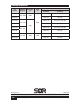
Process Connection
Use two wrenches when connecting process pipe: an 1-1/8 inch open-end wrench to hold
the hex port while connecting the process pipe; the other wrench to tighten the process
pipe or tube fitting.
When rigid process piping is used, it is important that no bending or torsional
forces be imposed on the pressure switch.