
Manual


Form 830 (03.13) ©SOR Inc.
1/12
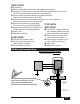
The 651 RF Admittance Single Point Level Switch is a level control which
uses dielectric constant and conductivity to detect the level of liquids,
slurries, granulars, and solids. When used with any of the RF Probes,
it will provide accurate switching for level processes.
The control features a fail-safe switch which reverses the operation of
the relay. An LED inside the housing lights when the process is touching
the probe. A sensitivity adjustment inside the control allows the user to
increase or decrease sensitivity as needed. Optional time delay feature
will delay switching on or off from 0 to 60 seconds.
651 RF Admittance
Single Point Level Switch
General Instructions
Registered Quality System to ISO 9001
Design and
specifications are
subject to change
without notice.
For latest revision, go to
www.sorinc.com
NOTE: If you suspect that a product is defective, contact the factory or the
SOR
®
Representative in your area for a return authorization number (RMA).
This product should only be installed by trained and competent personnel.
Table of Contents
Pre-Installation I/O Test and Calibration ....1
Installation ....................................... 3
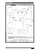
Electrical Connections .........................4
RF Probe Grounding Scheme .................5
Fail-Safe Mode ..................................6
Circuit Board Replacement ....................7
Sensor Replacement ...........................7
Control Drawings ............................ 8-9
Troubleshooting ............................... 10
Dimensions ................................ 11-12
Pre-Installation I/O Test and Calibration
Remove instrument from shipping box and visually inspect for obvious
physical damage. Report any shipping damage to the carrier. Report
any internal discrepancies to the factory representative in your area.
Record the serial number from the nameplate should conversation
with the factory be necessary.
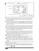
Remove housing cover.
Place instrument on an insulated surface or support so sensor does not touch a
conductive surface.
Ensure area is safe and observe normal precautions for exposed and powered PC board.
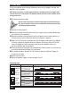
Apply proper line power per page 4, and observe LED. (See
)
h
g
)
.
o
us