
Instruction Manual


4/8
Form 948 (10.09) ©2009 SOR Inc.
Wiring Details
Ensure that wiring conforms to all applicable local and national electrical codes and install
unit(s) according to relevant national and local safety codes.
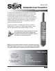
The Series 510 transmitter is designed to operate in a 2 wire, 4-20 mA system. A system
of this type requires that the measuring instrument alter the current consumption of an
electrical circuit in proportion to level (pressure) changes. The changes in current may
be measured using suitable instruments. Due to the design of the transmitter, it is un-
able to produce currents less than approximately 3.3 mA. Should the transmitter output
be “locked” at a fig ure of this order, it is indicative of a fault and the system should be
checked immediately.
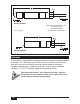
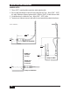
Schematic diagrams for incorporation of the transmitter into a control or display loop are
shown here. The sup ply voltage at the transmitter terminals must be between 10 and 32 VDC
(IS option 28 VDC max). Polarity of the transmitter wiring is essential for proper operation.
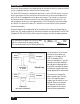
The transmitter will drive into a resistive load,
which is a function of the supply voltage.
This may be derived from the following formula:
R
L
(Max) = V
Supply
- 10V
20mA
Power
Supply
Red Wire
Blue Wire
White Wire
Transmitter
Milliammeter
4 - 20 mA
Case Ground
Power
Supply
Red Wire
Blue Wire
White Wire
Transmitter
Case Ground
To Display or
other Process Instruments
Resistive
load
Current Loop
-
-
As noted earlier, the minimum
current the transmitter can
supply is in the order of 3.3
mA. If a reading of this
nature is obtained, it is usually
indicative of a fault condi tion,
possibly due to damage to the
transmitter caused by overpres-
surization or negative pressure
being applied to the transmitter.
The red wire is the positive
power supply input, the blue
wire is the negative power
supply input and white is case
ground. Reverse connection
will prevent the transmitter
operating due to its internal
reverse polarity protection.