
User Manual

302 User Guide and Technical Information
10
v. 3.6 Features and specifications are subject to change. Visit www.sounddevices.com for the latest documentation.
Stereo Linking of Inputs 1 and 2
Stereo linking allows Inputs 1 and 2 to be controlled as a single, stereo input. This is useful when
stereo microphones or stereo line level signals are used with the 302. Stereo linking allows the user to
control the overall signal of both inputs with a single fader.
There are two modes of operation for stereo linking, X/Y link and MS stereo. Stereo linking is
activated in the Setup Menu.
X/Y Stereo Link
Inputs 1 and 2 can be linked as a stereo pair to simplify control when using stereo microphones.
X/Y stereo linking is set in the Setup Menu. When in X/Y stereo link operation, Inputs 1 and 2
Pan switches continue to control the signal routing for each respective channel. Channel 2’s Fader
controls the overall level of the stereo pair. Input 1 and 2’s Gain (trim) pots and High-Pass Filters
continue to act independently of each other. When linked, Channel 1 and 2’s Input Limiters are also
linked.
MS Stereo Linking
When MS stereo linking is selected in the Setup Menu, Inputs 1 and 2 are linked as an MS (Mid-
Side) stereo pair. MS is a popular stereo configuration because of its good spatial placement, mono-
compatibility, and surround compatibility.
The 302’s MS matrix uses Input 1 for the Mid signal and Input 2 for the Side signal. Input 2’s Fader
controls the overall gain of the MS stereo pair. Input 1’s Fader and both Input 1 and 2’s Pan switches
are disabled. Input 1 and 2’s Gain (trim) pots and High-Pass Filters continue to act independently of
each other. The Gain control for Inputs 1 and 2 are used to vary the Mid and Side levels respectively.
Using the Input 2 Gain is an effective way to control the stereo spread.
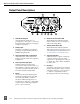
Inputs 4 & 5
When additional inputs are needed, such as when multiple wireless receivers are
used, the Return connector can be assigned to act as the input connector for Channels 4 and 5. This
functionality is set in the Setup Menu. See Setup Menu.
Several options are available for Inputs 4 and 5. Either or both of the inputs can be sent to the left,
right, or left and right output bus. Control the input sensitivity of Inputs 4 and 5 with the RTN L
(CH4*) and RTN R (CH5*) Trim controls adjacent to the RTN (Input 4/5*) 3.5-mm Female connector.
The RTN (Input 4 and 5) Input is an unbalanced stereo input that is suitable for tape or line level devices
only. There are no microphone preamps on Inputs 4 and 5.
To indicate that the Return connector is now used for Inputs 4 and 5, the 4/5 Channel Enabled LED
(on the output panel) illuminates.