
User Manual

302 User Guide and Technical Information
5
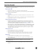
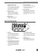
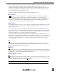
14. Headphone Selector Switch
Sets the signal source sent to
headphones. Options include: input PFL
1, 2, 3; left output bus; right output bus;
Mono (summed left and right); STereo
master; RTN - stereo monitor return;
MS-mono; MS-stereo; RTN-MS.
15. Headphone Volume
Adjusts the overall volume of the
headphones. NOTE: the headphone
output is capable of ear-damaging
levels. Take care when adjusting among
signal sources.
16. Headphone LED
Indicates signal overload in the
headphone and RTN circuits.
17. Battery Check Button
Press and hold to display the internal
and external battery levels on the output
meter. Battery level remains for two
seconds after button release
18. Power Switch/LED
Three-position switch, selects between
internal battery power or external DC
sources, middle position is off. Power
LED illuminates when power is on. LED
flashes when voltage reaches low limit.
See Powering.
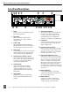
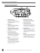
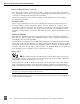
Input Panel Descriptions
1
2
3 4
5
1. XLR Inputs
Transformer-balanced channel inputs.
Pin-1 = ground; pin-2 = ‘hot’; pin-3 =
‘cold’. Can be unbalanced by grounding
pin-3 to pin-1 of the XLR connector.
2. Mic/Line Channel Switch
Selects the input level of the adjacent
connector. Mic level has 40 dB more gain
than line level.
3. Phantom/DYNamic/T-Power Selection
Selects the microphone powering type
of the adjacent input. DYN position
turns off all microphone powering. Mic
powering is selected per input. NOTE:
Use T-Powering only for T-Powered
microphones.
4. Phantom Voltage Selection
Selects between 48 V or 12 V phantom
voltage for all input channels. The three-
position switch uses two positions for 12
V, there is no difference between these
positions.
5. Headphone Output
3.5 mm TRS stereo headphone output.
Can drive headphones from 8 to 2000
ohms to required monitoring levels.