
User Manual


3) RTN Input
Unbalanced stereo 3.5 mm female con-
nector for Return audio input. Sleeve =
Ground, Tip = Left, Ring = Right.
4) X1 and X2 Outputs
Line, -10, or Mic level selected in the
Setup Menu section OUTPUTS. Pin-1
ground, pin-2 (+), pin-3 (-). Float pin 3 to
unbalance.
5) DC Input
Accepts DC voltages from 10–18 V for
powering. Pin 1 = Negative (–), pin 4 =
Positive (+).
6) XLR-3M Master Outputs
Balanced analog outputs on standard
3-pin XLR-3M connectors. Mic, Line, -10,
or AES (1,2 and 3,4 on L and R respective-
ly) selectable from Setup Menu section
OUTPUTS. Pin-1 ground, pin-2 (+), pin-3
(-). Unbalance by grounding pin 3 to pin
1.
7) Headphone Output
1/4-inch TRS stereo headphone connec-
tor. Can drive headphones from 8 to 1000
ohm impedances to very high levels. Tip
= left, ring = right, sleeve = ground.
8) CompactFlash Slot
Accepts approved CompactFlash cards
with the label-side toward the rear of the
633. Compatible with Type I and Type
II cards. High-speed UDMA cards are
recommended for higher track count re-
cording. See http://www.sounddevices.com/
approved for a list of approved media.
9) SD Card Slot
Accepts approved SD/SDHC/SDXC
cards with the notched corner oriented
toward the top of the 633. Insert until it
clicks securely in the slot. The card should
glide smoothly into the slot. Press to eject.
See http://www.sounddevices.com/approved
for a list of approved media.
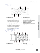
Rear Panel
B2 B1
Two battery mounts (“slots”) on the rear panel for Sony
©
L-Series type lithium batteries. Any capac-
ity supported. Battery slots labeled B1 and B2 in the diagram above correspond to the labels in the
Setup Menu section POWER. (See “Powering”, page 52)
633 User Guide and Technical Information
4
v. 1.02 Features and specifications are subject to change. Visit www.sounddevices.com for the latest documentation.
Panel Descriptions