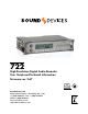
722 High Resolution Digital Audio Recorder User Guide and Technical Information firmware rev. 2.67 SATA 2.5" HDD Sound Devices, LLC E7556 State Rd. 23/33 • Reedsburg, WI • USA +1 (608) 524-0625 • fax: +1 (608) 524-0655 Toll-Free: (800) 505-0625 www.sounddevices.com support@sounddevices.
722 User Guide and Technical Information Table of Contents Quick Start Guide . . . . . . . . . . . . . . . . . . . . . . . . . . . . 3 Powering the Unit Menu Navigation Basics Connecting Audio Sources Routing Inputs to Tracks Recording Parameter Setup Recording Playback FireWire File Transfer Front Panel Descriptions . . . . . . . . . . . . . . . . . . . . . . 6 Panel Lock LCD Display Descriptions . . . . . . . . . . . . . . . . . . . .
722 User Guide and Technical Information Welcome Thank you for purchasing the 722. The super-compact 722 records and plays back audio to and from its internal hard drive or CompactFlash medium, making field recording simple and fast. It writes and reads uncompressed PCM audio at 16 or 24 bits with sample rates between 32 kHz and 192 kHz. It also writes and reads data compressed FLAC and audio compressed MP2 and MP3 files.
722 User Guide and Technical Information Quick Start Guide The 722 is an extremely powerful and flexible portable audio recorder. Before recording, familiarity with the product is essential. Several settings should be verified or set based on individual recording needs. Powering the Unit 1. Apply power to the unit by connecting the (included) removable, rechargeable Li-ion (lithium ion) battery to the back panel battery mount.
722 User Guide and Technical Information Routing Inputs to Tracks Before recording, inputs must be assigned to tracks. Each of the 722’s two inputs can be assigned to the two tracks (A, B). Sixteen possible routing combinations are shown on the front panel with four blue LEDs. Illuminated LEDs indicate input-to-track assignment. 1. Press and hold the STOP key then press the INPUT key to cycle through factory routing presets.
22 User Guide and Technical Information FireWire File Transfer Sound Devices strongly recommends shutting down equipment before connecting to or from any FireWire device with a connection that carries power (6-pin). Reports have come to our attention of isolated problems when hot-plugging IEEE 1394 (FireWire) devices. (Hot-plugging refers to making connections when one or more of the devices—including the computer—is on.
722 User Guide and Technical Information Front Panel Descriptions All settings of the 722 can be accessed and monitored through the front panel LCD and navigation keys. This allows the unit to be placed in a production bag along with field mixers and wireless transmitters and receivers. 1 2 3 4 5 6 7 8 9 10 11 12 29 28 27 26 25 24 1) 2) 6 v. 2.67 23 22 21 20 19 18 17 Digital Input LEDs Indicates the presence of digital signal on the respective input.
722 User Guide and Technical Information 10) 11) 12) 13) 14) 15) Power Key Press and hold to power up the 722. Press and hold to power down. 16) Fast Forward Key 17) Play Key Charge LED Indicates the status of the onboard battery charger. Flashes when external power is connected and battery is charging; solid when battery is fully charged. Power LED Indicates that the 722 is powered and available for operation. Flashes when the removable battery or external DC is in a low-voltage state.
722 User Guide and Technical Information 22) 23) 24) 25) Link LED Indicates that channels 1 and 2 are linked as a stereo pair. In link mode the channel 1 potentiometer controls gain, channel 2 potentiometer controls leftto-right balance. Inputs can be linked as either a stereo L/R pair or as a a MidSide (MS) pair.
722 User Guide and Technical Information LCD Display Descriptions 1 2 3 4 5 10 6 9 8 1) Battery Level Indicator Shows the voltage level of the removable rechargeable battery or external power sources. External power overrides internal power when present. Graphical bar for relative level and numeric indicator for precise voltage measurement.
722 User Guide and Technical Information 13 12 11 11) 12) 10 v. 2.67 24-Hour Time Counter 24-Hour time is displayed when the Setup Menu option Time Counter: Mode is set to 24h. The A-time and the 24-Hour Time Counter display can be exchanged if a large 24-Hour Time Counter display is needed. See 24-Hour Time Counter for details. Input 1/2 Level When input 1 or 2 gain is turned this indicates the gain level in dB for inputs 1 and 2.
722 User Guide and Technical Information Left Panel Connectors and Controls 3 1 4 2 5 8 6 7 1) XLR Input 1/AES3 Input 1&2 5) TA3 Master (L/R) Analog Outputs 2) XLR Input 2 6) Headphone Output Mic-Line-AES3 Input Switch 1 7) 3) 4) Dual function input connection. Input type set with switch (see #3). Active-balanced analog microphone- or line-level input for input 1. Transformer-balanced two-channel AES3 input (1 and 2). Same as Input 1 above for analog signals.
722 User Guide and Technical Information Right Panel Connectors and Controls 2 1 7 1) 2) 12 v. 2.67 AES3id Input Unbalanced digital input accepts two channel AES3 (or S/PDIF) on BNC connectors. Supports sample rates up to 200 kHz. 3 5 6 5) FireWire (IEEE-1394) Port Connection to a computer (Mac OS, Windows 2k/XP, Vista, Linux) to access the internal hard drive and CompactFlash volumes as mass storage devices.
722 User Guide and Technical Information Back Panel Descriptions 1 1) 2) 2 Security Slot Compatible with the Kensington® Security Slot specification. Useful for securing the recorder to a fixed object with a compatible computer lock. CompactFlash Slot Accepts CompactFlash medium with the label-side up. Compatible with Type I, Type II, and MicroDrives. 3 3) 4) 4 Battery Mount Accepts Sony® InfoLithium L- or MSeries removable rechargeable batteries, or batteries conforming to this mount.
722 User Guide and Technical Information Input Setup and Control The 722 has two inputs and two record tracks. Inputs are selectable between analog or digital sources. Analog inputs are connected with the balanced XLR connectors; digital inputs can be connected to either XLR Input 1 (AES3) or the BNC input (AES3id). Input Source Selection Input types are selected in pairs. Each input pair accepts analog or digital audio. The XLR input signal is selected with slide switch above the connector.
722 User Guide and Technical Information limiters will prevent unusually high input signal levels from clipping the analog input stage of the preamp. The front panel LIM LED ( ) shows that the limiter is engaged. Limiter activity is indicated by additional front panel LEDs, one for each input channel ( ). The input limiters are active only with mic-level inputs. The limiters are engaged by (factory) default. When limiters are engaged, audio on channels 1 and 2 is limited to -6 dBFS.
722 User Guide and Technical Information tion upon input two. Engaging or disengaging phantom power or the high pass filter on input two causes no effect on input one. If MS stereo linking is selected for inputs, program sent to tracks and headphones will be L/R stereo program. To record discrete M and S signals, do not link for MS, but monitor the MS signal in headphones. Things to consider when Linking Input 1,2 as MS: • Digital Inputs cannot be linked as an MS pair.
722 User Guide and Technical Information Switch is pressed or or the check mark is selected. The amount of delay available is dependent on the sampling frequency in use. Sample Frequency Maximum Amount of Delay Available (per input) 32, 44.1, 47.952, 48, 48.048 kHz 30 mS 88.2, 96, 96.096 kHz 15 mS 176.4, 192 kHz 7.5 mS Input delay can be useful for time aligning input signals from differing sources. For example, digital wireless mics that have a processing delay in their outputs.
722 User Guide and Technical Information To assign custom input routing: 1. Press the input key until Input Routing is displayed in the LCD display. arrow indicates highlighted input is assigned to highlighted track select to exit menu and apply selected routing selet to move up and down menu select to remove input assignment 2. Press the EDIT soft button ( 3. Using either the Rotary Switch or the up and down arrows, navigate to desired input-to-track combinations. 4.
722 User Guide and Technical Information Sampling Rate and Bit Depth When recording the 722 generates uncompressed PCM audio WAV files in the Broadcast Wave File format at the user-selected sampling rate and bit depth. The 722 LCD calculates available recording time based on the sampling rate, bit depth, number of tracks set for recording and the selected storage media available capacity. See the Calculating Recording Time later in this guide to estimate record time.
722 User Guide and Technical Information The 722 has 24 bit analog-to-digital converters. To obtain 16 bit recording the 722 can be set to dither 24 bit digital signals to 16 bit. The 722 uses a proprietary pseudo-random dither routine for accurate bit rate reduction. Dither can be defeated in the user menu. Without dither, 24 bit audio is truncated to 16 bit, meaning the least significant 8 bits are discarded. Once a file is recorded its sampling rate and bit depth can not be changed in the recorder.
722 User Guide and Technical Information C. Link – Multi-Unit Linking The proprietary C. Link (control link) connection allows multiple 702, 702T, 722, and 744T recorders to be connected and clocked together. C. Link also enables connection to external keyboards and switch contacts using the CL-1 Remote Control and Keyboard Interface. When linked, 7-Series recorders have a master/slave relationship. The master recorder and the slave unit will share sample accurate start and stop record times.
722 User Guide and Technical Information Outputs – Analog and Digital The 722 has two discrete output buses, the Analog Output Bus (Bus 1) and the Digital Output Bus (Bus 2). Each side (left and right) of the two-channel buses are assigned their audio sources independently, enabling the 722 to feed multiple audio devices with unique program content. The chart below shows the audio sources available for the analog and digital output buses. The audio source for each output is selected in the setup menu.
722 User Guide and Technical Information Headphone Output The 722 headphone output is a flexible tool for monitoring audio in the field. The 722 allows the user to monitor inputs, tracks, and post-record tracks in a number of combinations. MS stereo monitoring is also available in headphones. The headphone output is independent of the Master Output Bus and the Output Bus 2—audio sources can be routed to headphones independent of routing assignments to output buses.
722 User Guide and Technical Information HP Sources Description Tracks A, B (MS) Stereo monitoring of discrete M (mid) and S (side) track pairs. Highlighted media is source of monitor program. Upon playback will function as MS track monitor. Monitor A,B (MS) Stereo monitoring of playback (post-record) discrete M (mid) and S (side) track pairs. Highlighted media is source of monitor program. When not in playback, headphones have no program.
722 User Guide and Technical Information Headphone Favorite Selection If “Selects Favorite Mode” is selected from the choices above, pushing the Rotary Switch selects the assigned “Headphone Favorite” source. This feature is helpful to quickly return to a selected headphone monitoring selection while recording or playing. One of the available headphone selection can be selected as the headphone favorite. Headphone Playback Mode The user may select a headphone source for automatic selection upon playback.
722 User Guide and Technical Information The meter uses energy efficient LEDs viewable in full sunlight. The 722 output meter is unaffected by shock or extremes in temperature and humidity. Meter ballistics are setup menu selectable among VU, Peak, Peak-Hold, VU + Peak and VU + PeakHold. The meter uses a compound metering scale which increases meter resolution in the most important part of the scale. From -50 to -40 dBFS, each LED segment equals approximately 10 dB.
722 User Guide and Technical Information Peak LEDs input peak LEDs input signal present LEDs headphone peak LED In addition to the main LED output meter, peak LEDs show input peaks, track peaks, and headphone peaks. Input Peak The 722 has a peak LED associated with each input. These LEDs illuminate when input signal reaches –3 dBFS. There is no user-adjustment to the Input Peak LEDs. These LED’s also function as indicators of input mute activity (see Input-to-Track Routing).
722 User Guide and Technical Information The tone oscillator can be activated anytime during recording by setting the Tone: Record Lock feature in the Setup Menu. Press the Tone key anytime to generate a tone signal. Please note that when enabled, any slight press of the tone key will generate tone and override any program material where tone has been routed to, including record tracks. LCD Contrast & Backlight, LED Brightness LCD contrast is setup menu controlled.
722 User Guide and Technical Information 24-Hour Time Counter By default, the 24-Hour Time Counter is displayed below the big A-Time. The position of the A-time and the 24-hour time counter numbers can be exchanged in the Setup Menu option Time Counter: Display. When Big 24h time is selected, the 24-Hour Time Counter value is displayed in the main numeric display. If Time Counter Mode is turned off, A-time is shown as large numbers, even with Big 24h time is set.
722 User Guide and Technical Information During recording, subsequent presses of the record key can perform one of three setup-menu-selected actions: • no action, • new cue - cue markers are set within the file being written, • new file - a new file is started with each press of the record key, the take counter is increased by one. When removing the CompactFlash from the 722, always observe the amber CF activity LED. If it is lit, wait until it goes out before removing the CF.
722 User Guide and Technical Information 2. Press the REC key to begin recording. 3. Pause the recording at any time by pressing the STOP key once. When paused the absolute time and Record LED will flash. 4. Press the REC key again to continue recording. 5. Press the STOP key twice will finalize the recording. At this point, the file is available for Playback and the next press of the REC key will begin recording the next incremented take.
722 User Guide and Technical Information Audio File Formats The 722 records audio to the industry-standard Broadcast Wave file format, either monophonic or polyphonic, MP2, MP3, or FLAC. Files created by the 722 receive the .WAV, .MP2, .MP3, .FLAC file extensions. The 722 will read files with the .BWF extension. .WAV The 722 has two file type options for recording WAV files, mono and poly. Select the file type in the Setup Menu option REC: FILE TYPE.
722 User Guide and Technical Information .MP2 MPEG-1 Layer II is a lossy compression algorithm often used for speech recording. What to consider when recording to MP2: • • • • • BEXT or iXML mono recordings are not allowed with bit rates above 192k limits your sampling rate to 48 kHz limits your bit depth to 16 bit limits recording to only one storage medium at a time .MP3 MPEG-1 Layer III is a lossy compression algorithm often used for music.
722 User Guide and Technical Information Using an external keyboard via the CL-1 Remote Control and Keyboard Interface the entry of notes is much quicker than using the Rotary Switch. Post-record metadata editing can be performed using a Mac OS or Windows based computer with Sound Devices Wave Agent Beta. See Wave Agent Beta for more details.
722 User Guide and Technical Information PCM Audio Uncompressed digital audio is expressed numerically by two measurements, bit depth and sampling frequency, such as 16-bit/48 kHz. These two numbers are used to compute the data rate of uncompressed audio. Audio Data Rate = Bit Depth x Sampling Frequency In the example below the data rate of a single 16-bit/48 kHz audio stream is computed in megabytes per minute. Division by 1,048,576 converts from bits to megabits.
722 User Guide and Technical Information Scene Name/Number Scene names are made with alphanumeric characters, including “_ ” and “-” can can be any length between zero (0) and nine (9) characters in length. Scene numbers are helpful to match audio with the corresponding scene in a production. Scene names can also be used to identify other items, including recording date, artist name, or any other descriptor as required.
722 User Guide and Technical Information 3. The Rotary Switch or the soft keys are used to choose characters/numbers. Press the Controller or hit the soft check key to save the character and move to the next position.
722 User Guide and Technical Information • Mac OS and Windows compatible Wave Agent is available as a no-charge software download for either Mac OS or Windows. http://www.sounddevices.com/download/waveagent.html File Management The 722, like a computer, saves audio recordings to a file system containing files and folders. The 722 formats its internal hard drive, CompactFlash medium, and attached external drives as single drives named “722 INDD”, “722 CF”, and “722 EXTHDD,” respectively.
722 User Guide and Technical Information A hierarchical view of files generated by the 722 is below. 722 1 1 1 1 The FALSETAKES, SOUNDDEV, and TRASH folders are automatically generated. SOUNDDEV is not viewable from the 722 File Viewer. FALSETAKES SOUNDDEV A TOP-LEVEL folder sits in the root directory. This folder can be negated by choosing in the menu File: Folder Options. TRASH TOP-LEVEL 1 A MID-LEVEL folder can be used as a sub-folder.
722 User Guide and Technical Information File detail is shown at the right side of the display. The center divider points to the file selected for information viewing.
722 User Guide and Technical Information Setting/Clearing Flag Bits Pressing the tone key in the File Viewer display opens the “Set or Clear Flag Bit” screen. The options for setting or clearing flag bits include: set or clear the selected file, set or clear all the files in the current folder, or set or clear all files on the volume. All files created by the 722 have their archive bit set to on. Automatic Flag Clearing The recorder can be set to clear the flag bit of copied files automatically.
722 User Guide and Technical Information File Deletion Any file or folder on either internal hard drive or CompactFlash can be deleted. Permanently deleting files is a two-step process. Similar to Mac OS and Windows operating systems, the 7-Series uses a “trash” folder to temporarily hold files which have been deleted. To send a file to the trash, perform the following: 1. Press the HDD button to enter the File Viewer. 2. Navigate to the file to be deleted. 3. Press the soft key marked OPTIONS. 4.
722 User Guide and Technical Information Take Number Incrementing To advance to a higher take number hold the STOP button and press FastForward. The file name to be recorded is indicated above the file time. Indicates active take Indicates next upcoming take Take List The take list shows a sequential listing of the last 200 recorded files, without regard to what folder they have been recorded in. The first file in the list, marked with an * indicates the file name of the next recorded take.
722 User Guide and Technical Information To quickly identify the last recorded take as Circled or as No Good, perform the following steps: 1. Press the STOP key to end recording. 2. Press and hold the STOP key down, then press the LCD Backlight key to enter the Take Status Menu. 3. Press the soft Circle (Menu) key to mark the take as Circled or press the soft No Good (HDD) key to mark the take as No Good. The check mark appears in the selected box and the 722 automatically returns to the Main Display.
722 User Guide and Technical Information Formatting The drive installed in the 722 is formatted at the factory as a single-partition FAT32 volume. If a drive with multiple partitions is installed, the 722 will only “see” the primary partition. The 722 can only address one partition. As a matter of routine maintenance, periodic re-formatting of the 722 hard drive is recommended. Formatting the hard drive rebuilds the FAT (file allocation table) and erases any audio or other data files present on the medium.
722 User Guide and Technical Information Drive Replacement The internal hard drive can be removed and replaced if the drive fails or if a different capacity drive is needed. The internal hard drive is not a swappable medium. Its multi-pin connector is not rated for repeated insertion and removal cycles and may be prone to breakage with repeated cycling. In typical service conditions Sound Devices recommends hard drive replacement every three years.
722 User Guide and Technical Information If the recorder is used in applications subject to extreme motion, Sound Devices recommends recording to CF medium only. The hard drive will park its write heads to reduce the chance of failure. Like all electrical devices, the higher the ambient temperature the shorter the drive’s operational life. Therefore, take care to observe the specified temperature rating. There is also a risk from sudden temperature changes, which can create condensation inside the drive.
722 User Guide and Technical Information to measure the throughput speed of CF medium. Measured numbers greater than 3000 KB/s can reliably write 24/192 audio. Not all CF medium can sustain write speeds for reliable 192 kHz recording. Use the speed test utility to make certain that installed medium can support the selected number of tracks at 192 kHz.
722 User Guide and Technical Information 722 will prompt the user to format the drive. If the drive is already formatted as a FAT32 volume the drive will be ready to be selected as a storage medium. The front panel drive LED will illuminate to show which drives are available for recording. To reformat an attached drive, follow the same procedure as formatting the internal hard drive, substituting the external drive menu selection for the internal hard drive.
722 User Guide and Technical Information File Transfer – FireWire FireWire port FireWire cable - 744T to computer The 722’s FireWire (IEEE-1394) port makes transferring of recorded files to a computer quick and easy. When connected to a computer, the internal hard drive and CompactFlash card of the 722 will mount to a Mac OS X or Windows computer as a local, removable mass storage volume.
722 User Guide and Technical Information To disconnect the 722 from FireWire: 1. Make certain that any software applications that reference the 722 drive are closed and that all file copy functions to and from the 722 have completed. 2. In Mac OS X highlight the drive icon on the desktop and select drag the drive icon to the trash in the dock. 2. In Windows, right-click the drive icon and select “eject.” 3. The cable between the computer and 722 can now be disconnected.
722 User Guide and Technical Information DC input uses a 4-pin Hirose connector (Part # HR10-7P4P). There are two connection options available. External DC Input Wiring Operation pin-2 to negative (–) pin-3 to positive (+) operates the on-board Li-ion charger when the unit is both turned on and off. Use when plugged into AC power pin-1 to negative (–) pin-4 to positive (+) operates the on-board Li-ion charger only when the unit is turned on—there is no external current draw when powered off.
722 User Guide and Technical Information In addition to the internal record timer, the auto functions (power on/begin record/power off) can be used for more extensive unattended recording control. Using an outboard timer attached to a DC supply the 722 can be placed and activated to record events including EFX or nature, and for surveillance applications. Pin-3 (+) of the external DC input must be wired in order for the External Power Functions to operate.
722 User Guide and Technical Information Firmware Upgrades The 722 uses upgradable EEPROM (electrically erasable programmable read-only memory) to hold the unit’s operating system software, or firmware. Firmware is the source code which controls all aspects of the device, including: signal routing, signal processing, menu options, LED’s, controls, and data ports. Version Information During manufacturing the unit’s hardware revision number and serial number are burned into a protected area of the EEPROM.
722 User Guide and Technical Information CL-1 Remote Control and Keyboard Interface The CL-1 Remote Control and Keyboard Interface is an available hardware accessory to interface with PS/2 compliant computer keyboards and enable external devices to control the 722. When using the CL-1, front panel controls and menu selections on the 722 can be mapped to keyboard shortcuts, allowing for full keyboard control of the recorder.
722 User Guide and Technical Information End Setup User Interface Menu - Moves to the bottom of the list.
722 User Guide and Technical Information 2. Select an unassigned shortcut number for programming. If a duplicate key sequence is selected the lowest shortcut number action takes place. The example below shows the F1 key being reprogrammed. 3. After selecting a key sequence select the desired Setup Menu item or action. The example below shows the reprogramming of the F1 key to change the sampling rate to 48048. Specific Setup Menu options can be programmed if multiple options are available.
722 User Guide and Technical Information Logic Inputs Configured as a switch-closure input, a pin can be connected to a switch that a user has wired to assigned contact. This switch can then trigger the 744T to begin recording. Other functions can be assigned as well from the Setup Menu. The switch-closure on a given pin of the CL-1 can be thought of as just another key on the keyboard. Anything that can be assigned to a key can also be assigned to a switch.
722 User Guide and Technical Information Film Preset Reporter Preset Music Preset 722 Presets Factory Preset Rec: Pre-Roll Time 2 Sec 2 Sec 2 Sec 2 Sec Rec: Dither Off Off On On Rec: Timer Start Disabled Disabled Disabled Disabled Rec: Timer Stop Disabled Disabled Disabled Disabled Rec: Record Indicator Normal Numbers Normal Numbers Normal Numbers Normal Numbers Rec: Record Pause Disabled Disabled Disabled Disabled Input: Routing 1->A / 2->B 1->A / 2->B 1->A,B / 2->A,B
722 User Guide and Technical Information Film Preset Reporter Preset Music Preset 722 Presets Factory Preset Meter: Stealth Mode Off Off Off Off HP: Rotary Sw Function Selects Favorite Mode Selects Favorite Mode Selects Favorite Mode Selects Favorite Mode HP: Monitor Modes 01> Inputs 1,2 02> Tracks A,B 03> Input 1,1 04> Input 2,2 05> Monitor A,B 01> Inputs 1,2 02> Tracks A,B 03> Input 1,1 04> Input 2,2 05> Monitor A,B 01> Tracks A,B 01> Inputs 1,2 02> Tracks A,B 03> Input 1,1 04> Input 2
722 User Guide and Technical Information Setup Menu The setup menu controls a wide range of parameters for the 722, including all audio routing and recording settings. The setup menu is a single, flat architecture with no sub-menus, easing navigation. Each setup controls a specific parameter with several selections. The chart below shows the setup number, a description of the control, and the menu options available.
722 User Guide and Technical Information # 10 Setup Name Rec: Take Reset Mode Setup Description Defines when take numbers are reset. Reset brings take number to <1>. Setup Options • Never - take numbers do not reset • When scene is changed - take resets when scene name is changed • When daily folder changes - takes reset on new day • Either scene or daily - takes reset on either change 11 Rec: Pre-Roll Time Selects the amount of pre-roll time the 722 will add to the beginning of each file. 0–10 sec.
722 User Guide and Technical Information # Setup Name Setup Description Setup Options 29 Line Input 1,2: Gain Control When inputs 1 and 2 are in LINE input mode, selects whether the gain setting is controlled by the front panel knobs or by the menu sensitivity settings below. • Use front panel knobs • Use sensitivity settings 30 31 Line Input 1: Gain Line Input 2: Gain Adjusts the input sensitivity of line-level inputs when set to Use Sensitivity Settings. Adjustable from -6 dB to +18 dB in 0.
722 User Guide and Technical Information # Setup Name Setup Description 46 47 Output 2 Left: Source Output 2 Right: Source Selects the signal source for output bus 2 sent to digital output bus 2. • Input 1 • Input 2 • Track A • Track B • Input 1+2 • Track A+B 48 Output 2 L,R: Attenuation Selects the attenuation level of the signal output to bus 2. Selectable from 0 to –40 dBFS 49 Digital Output: Mode Selects whether or not the consumer SPDIF bit is applied or not in the AES3id output.
722 User Guide and Technical Information # Setup Name Setup Description Setup Options 62 HP: Favorite Mode Selects the audio source monitored when the Rotary Switch is pressed during recording or playback. Inputs 1,2 Tracks A,B Monitor A,B Input 1,1 Input 2,2 Track A,A Track B,B Monitor A,A Monitor B,B Inputs 1,2 (MS) Tracks A,B (MS) Monitor A,B (MS) Inputs 1+2,1+2 Tracks A+B,A+B 63 HP: Playback Mode Selects the audio source sent to headphones upon playback.
722 User Guide and Technical Information # Setup Name Setup Description Setup Options 79 EXHDD: Empty Trash Allows user to delete files previously sent to the trash as well as false takes. • Empty Trash • Empty False Takes • Empty both 80 Balance Cal Calibrates the center position of the input 2 pot when used as the balance control for MS recording. Place balance control to center and press to select.
722 User Guide and Technical Information Front Panel Button Shortcuts To speed navigation the 7-Series has numerous navigation “shortcuts”. For combinations, hold down the first identified key and continue to hold while pressing the next keys. Function Record Tone Jam Menu Button Lock Key Sequence Action Record and Tone + In the menu File: Marker Mode must be set to Markers Disabled. While recording hold the REC button and press the tone button. Tone will be active as long as the tone button is held.
722 User Guide and Technical Information Connector Pin Assignments Each connector type, electrical characteristics, and pin assignment is shown below. 68 Connector Pin Assignments Notes XLR (Analog Inputs) 1 – ground 2 – signal (+) 3 – signal (-) 7.
722 User Guide and Technical Information Specifications System Sampling Frequency internal: 32, 44.1, 47.952, 48, 48.048, 88.2, 96, 96.096, 176.4, 192 kHz external: 32–192 kHz via word clock input Internal Data Path and Processing 32 bit, 192 dB dynamic range A/D, D/A Converters 24 bit, 192 kHz sample rate maximum.
2 User Guide and Technical Information Inputs/Outputs – Digital AES3-id 75 ohm, 0.5 V p-p, S/PDIF compatible with RCA adapter Digital Storage Internal hard drive SATA interface 2.5-in hard drive 4200–7200 RPM supported, FAT32 formatted, up to 2 TB addressable serial numbers below 471309092000 use ATA-5 interface 1.8-in or 2.
722 User Guide and Technical Information Accessories Included Accessories The accessories below are included with the 722: • • • • • • Universal In-Line Power Supply, 100–240 VAC input, 12 VDC, 45 W output (XL-WPH3) Li-ion removable rechargeable battery, 4600 mAh 3.5 mm to 1/4-inch jack for headphone output extension (XL-14) C.
722 User Guide and Technical Information 72 XL-DVDRAM An external bus-powered FireWire DVD Multi-drive. Based on the slotloading Panasonic UJ-85 drive mechanism, the XL-DVDRAM is used with a 7-Series recorder to record directly to optical disk or as a post-record storage volume. XL-H Bare Hirose 4-pin locking DC connector (HR10-7P-4P). XL-LCD Protective, clear Lexan LCD cover for 7-Series Digital Recorders. Protects the LCD glass from scratches and water. Kit of four covers.
722 User Guide and Technical Information CE Declaration of Conformity According to ISO/IEC Guide 22 Sound Devices, LLC 300 Wengel Drive Reedsburg, WI 53959 USA declares that the product, 722 Professional Digital Audio Recorder is in conformity with and passes: 89/336/EEC EMC Directive EN55103-1, 1997 EMC-product family standard for audio, video, audiovisual and entertainment lighting control apparatus for professional use.
722 User Guide and Technical Information Software License End-user license agreement for Sound Devices 7-Series Embedded Software / Firmware Important Read carefully: This Sound Devices, LLC end-user license agreement (“EULA”) is a legal agreement between you (either an individual or a single entity) and Sound Devices, LLC for the Sound Devices, LLC software product identified above, which includes computer software, embedded software, and may include associated media, printed materials, and “online” or el
722 User Guide and Technical Information Limitation of Liability LIMITATION ON SOUND DEVICES’ LIABILITY. SOUND DEVICES, LLC SHALL NOT BE LIABLE TO THE PURCHASER OF THIS PRODUCT OR THIRD PARTIES FOR DAMAGES, LOSSES, COSTS, OR EXPENSES INCURRED BY PURCHASER OR THIRD PARTIES AS A RESULT OF: ACCIDENT, MISUSE, OR ABUSE OF THIS PRODUCT OR UNAUTHORIZED MODIFICATIONS, REPAIRS, OR ALTERATIONS TO THIS PRODUCT, OR FAILURE TO STRICTLY COMPLY WITH SOUND DEVICES, LLC’S OPERATING AND INSTALLATION INSTRUCTIONS.
722 User Guide and Technical Information Warranty and Technical Support Warranty & Service Sound Devices, LLC warrants the 722 Recorder against defects in materials and workmanship for a period of TWO (2) years from date of original retail purchase. This is a non-transferable warranty that extends only to the original purchaser. Sound Devices, LLC will repair or replace the product at its discretion at no charge. Warranty claims due to severe service conditions will be addressed on an individual basis.
722 rev. 2.67 - Printed in U.S.A.