
User Manual


MixPre-D User Guide and Technical Information
12
v1.0 Features and specifications are subject to change. Visit www.sounddevices.com for the latest documentation.
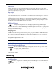
Connector Pin Assignments
Connector Pin Assignments Notes
XLR-F
Analog Inputs 1-2
1 – ground
2 – signal (+)
3 – signal (-)
3.3k ohm input impedance, Mic- and Line-level Transform-
er Balanced. For unbalanced, pin 1 and pin 3 tied together
= ground, pin 2 = positive.
3.5 mm
Return Input
tip – signal L
ring – signal R
sleeve – signal ground
Mates with 3.5 mm TRS jack. Signal is unbalanced.
XLR-M
Master Outputs/
AES Output
1 – ground
2 – signal (+)
3 – signal (-)
Transformer balanced, Output Level is selectable using
switch between Mic or Line-level. For unbalanced, pin 1 =
ground, pin 2 = positive, pin 3 = floating (unconnected).
Balanced AES3 Out on Right XLR connector, 110 ohm,
2 V p-p, AES3 and S/PDIF compatible with RCA adaptor.
3.5 mm
Tape Output
tip – signal L
ring – signal R
sleeve – signal ground
Mates with 3.5 mm TRS jack. Signal is unbalanced.
TA3-M
Stereo Mic Output
1 – ground
2 – left signal
3 – right signal
Unbalanced stereo output for interconnection to stereo
mic inputs. Mic level (-36 dBu). Mates with Switchcraft
TA3F-type connector.
1/4-inch Female
Headphone
Made In
Reedsburg, Wisconsin
USA
www.sounddevices.com
This device complies with the
FCC Rules, Part 15, Class B.
1
2
3
4
5
6
7
8
788T
A
B
C
D
E
F
BFS
d
0
IN
CF
EX
ARM ARM
BFS
d
0
INPUT
PWR
MENU
HDD
REC
R
L
KEYBD
OUT
INC.LINK
AES I/O, GPIO, PWR
COMPACT FLASH
MENU
SELECT
1
2 3
4
5,6
UNBAL
ANALOG BAL LINE OUTS
FW800
FW400
USB
BAL AES
OUT
1,2 3,4
TIMECODE
SYNC
WORD / VID IN
DC IN
10-18V
PIN 4
PIN 1
( )
( )
+
-
WORD OUT
tip – signal L
ring – signal R
sleeve – signal ground
Mates with 1/4-inch TRS jack.
Hirose 4-pin
DC Input
1 – ground
2 – not connected
3 – not connected
4 – DC (+)
10-17 Volt DC input. Mates with Sound Devices XL-NPH
and XL-WPH3 powering accessories. See Accessories for
details.
Specications
Frequency Response
20Hz - 30 kHz, +0.2, -0.5 dB (relative to 1 kHz level with 150 ohm source, gain controls
set at 50%)
Equivalent Input Noise
-126 dBu (-128 dBV) max. mic in to line out (150 ohm source, flat weighting, 22 Hz - 22
kHz bandwidth, gain control set at 50% or higher, phantom power off)
Input Clipping Level
-10 dBu min. (mic level) +28 dBu min. (line level)
Gain
• Line to Line, max: 26dB
• Line to Mic, max: -14dB
• Mic to Mic, max: 26dB
• Mic to Line, max: 66dB
• Unbalanced mic TA3 relative to Line out: -36dB
Dynamic Range
110 dB min., mic input to line output
THD + Noise
0.05% max. (from 50 Hz to 22 kHz @ +4 dBu output level)
Common Mode Rejection Ratio
100 dB min. at 80 Hz, 60 dB min. at 10 kHz
Inputs
Transformer-balanced, 2k mic input impedance, 16k line input impedance
Outputs
• XLR-Line/Mic: active-balanced, 100 ohm output impedance
• XLR-AES3: balanced, 110 ohm, two-channel, on right XLR connector
• TA3: unbalanced mic-level output, pin-2 left, pin-3 right, pin-1 ground, 200 ohm output
impedance
• Tape (3.5 mm) Unbalanced, tip-left, ring-right, sleeve-ground, 2.1k ohm output imped-
ance
Output Noise
-100 dBu (-102 dBV) max. (22 Hz - 22 kHz bandwidth, flat filter)
High Pass Filters
80 Hz or 160 Hz (switch selectable), 6 dB per octave
Phantom Power
12-volt through 680 ohm resistors or 48-volt through 6.8 k resistors (switch selectable)