
User Manual


MixPre-D User Guide and Technical Information
3
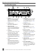
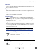
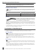
Side Panels Description
11
42 7 7 10
9866
2 5
3
1) XLR Inputs
Transformer balanced input stage. Pin 1:
ground; Pin 2: ‘hot’ (+); Pin 3: ‘cold’ (-).
Can be unbalanced by grounding pin 3
to pin 1 of the XLR connector.
2) Mic/Line and Phantom Power Switch
Selects the input level of the adjacent
XLR input. Left: (48V) mic level with
phantom power; Middle: (MIC) mic
level without phantom power; Right:
(LINE) line level. Mic level has 40 dB
more gain than line level.
3) Stereo Mic-level Output
Unbalanced stereo signal on a TA3 con-
nector. Signal from this output is mic
level (-36 dBu). Pin 1: ground; Pin 2: left;
Pin 3: right.
4) Stereo Line-level Output (Tape Out)
Unbalanced, stereo, 3.5 mm output
connector. Signal from this output is
aux level (-10 dBu). Tip: left; Ring: right;
Sleeve: ground.
5) 12V Phantom LED
Illuminated: phantom power is set to 12
V; Off: phantom power is set to 48 V.
6) XLR Outputs
Active-balanced outputs. Mic or Line
switchable. Right output can also be set
to AES. Pin 1: ground; Pin 2: ‘hot’ (+);
Pin 3: ‘cold’ (-).
7) XLR Output Switch
Sets level of output XLRs. Left: (MIC)
mic level (-40 dB); Middle: (LINE) line
level; Right: (AES) AES digital. The AES
setting is available on the right output
only. AES signal carries 2 channels on
one balanced connector.
8) USB Port
USB connector for interconnection with
the computer. USB 1.1 and 2.0 compli-
ant.
9) Return Input
Unbalanced, stereo, 3.5 mm input con-
nector. Feeds return signal to monitors
or 3,4 Inputs. See Inputs 3 and 4. Tip: left;
Ring: right; Sleeve: ground.
10) DC Input
Accepts input voltage from 10 to 17
V for mixer powering. Pin 1: negative
(-); Pin 4: positive (+). External DC is
isolated (floating) from the rest of the
circuitry.