
User Manual


MixPre-D User Guide and Technical Information
5
High-pass Filter
Each input of the MixPre-D has a two-position high-pass filter. High-pass (or low-cut/low frequency
roll-off) filters are useful for removing excess low frequency energy in audio signals. Wind noise is a
common unwanted low frequency signal and a high-pass filter is effective for reducing wind noise.
For most audio applications engaging the high-pass filter is beneficial, since little usable audio infor-
mation exists below 80 Hz, especially for speech reproduction.
The MixPre-D’s high-pass filters feature a 6 dB/octave slope with either 80 Hz or 160 Hz corner (-3
dB) frequencies. The 160 Hz setting is used when aggressive filtering is required. The MixPre-D’s
high-pass circuit is unique because of its placement before any electronic amplification. Most mixer’s
high-pass circuits are placed after the mic preamp, where all of the high-energy low-frequency
signals get amplified. Because the MixPre-D’s circuit cuts low-frequency signals before amplifying,
higher headroom is achieved in presence of signals with a high amount of low-frequency energy.
When possible, attempt to equalize at the sound source with microphone selection, use of wind-
screens, microphone placement, and on-board microphone filtering. Many microphones have on-
board high pass filters, and the high-pass filters on the MixPre-D can be used in conjunction with the
microphone’s filters to increase the filter’s slope.
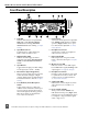
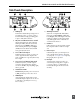
The three available high-pass filter settings are switched for each input by pressing the Input Button
for the adjacent input. The two blue High-pass Filter LEDs for each input indicate the setting of the
high-pass filter for the adjacent input.
Limiters
The MixPre-D Limiters act solely as “safety” limiters. Activate the Limiters using the front panel
“LIM” switch. Both input and output limiters are active, with input limiters preventing overload of
the input stage and output limiters preventing the MixPre-D from overloading the next device in the
signal chain.
In normal operation, with a properly set gain structure, the limiter threshold is only occasionally
reached. In the presence of extremely high input signal levels, such as in high SPL environments,
the limiter(s) activate to prevent the input signal from clipping. The limiters have no effect on audio
below the set threshold.
When Inputs 1 and 2 are linked as a stereo pair, the limiters also link; gain reduction is equal for both
inputs.
To change the threshold of the limiters, hold down both the Input 1 Button and the Input 2 Button
and turn the Headphone Controller.
Pan Switch
The pan switches assign inputs to the channels of the output bus. Inputs can be sent to the left,
right, or both outputs equally. The MixPre-D features excellent “off-attenuation” in the left and
right positions. With the use of the pan switches, separate mixes can be sent to the left and right out-
puts. For example, a summed mono mix of both inputs can be sent to the right output while a single
input can be sent to the left output.
Inputs 3 and 4
Each channel of the Tape Return input can be routed to various locations. When additional inputs
are needed (such as when multiple wireless receivers are used) the Tape Return channels can be
independently routed to the main output bus of the MixPre-D to act as additional inputs (3 and 4).