
Instruction Manual

MM-1 User Guide and Technical Information
5
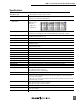
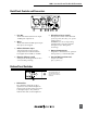
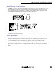
Back Panel Controls and Connectors
1
2
6
3
4
75
1) Line Out
Transformer-balanced line-level output.
+22 dBu peak output level.
2) Mic In
Transformer-balanced XLR input accepts
microphone level signals.
3) Balanced Monitor Input
Active-balanced ¼-inch connector
accepts balanced or unbalanced line
level signals from -10 dBu to +24 dBu.
4) Phantom Voltage Switch
Selects phantom voltages between 48 V
or 12 V for mic powering.
5) Microphone Power Switch
Three-position switch selects Phantom
power, T-power (12 Volts), or no power
(DYN position).
WARNING: Do not use T-powering
with phantom powered or dynamic
microphones (see “Microphone
Powering”).
6) Battery Compartment
Requires two AA batteries for operation.
Insert positive (+) end of battery first
7) External DC Input Connector
Accepts 5–17 VDC,
pin (+), sleeve (–). .
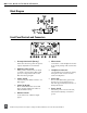
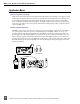
Bottom Panel Switches
1
The bottom panel switches are
accessible when the belt clip is
removed. Use a 1/16-inch allen-
head wrench.
1) DIP Switches
The “Split Ear” setting allows the a
signal to be sent to the left headphone
earpiece and a monitor signal to be sent
to the right earpiece. Also, S2-B can
mute the mic audio to the headphones.