
User Manual

MM-1 User Guide and Technical Information
4
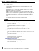
Features and specifications are subject to change. Visit www.sounddevices.com for the latest documentation.
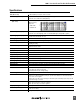
Block Diagram
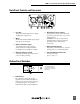
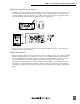
Front Panel Controls and Connectors
1
6
7
2
3
4
5
8
9
1) Preamp Gain Switch (Rotary)
Selects the amount of gain from input to
output, adjustable in 11 increments.
2) High-Pass Filter Switch
Three-positionswitchinsertsan80Hz
or160Hzcornerfrequencylter,6dB
per octave. Off position removes the
filter from the signal path.
3) Limiter Switch
Activatesthepeaklimiter.Limitsto+17
dBuoutput.
4) Limiter/Peak LED
Bi-colorLEDilluminatesredat3dB
below clipping; illuminates amber to
indicate limiter activity.
5) Monitor In Gain
ControlsthelevelofMonitorInput
signal.
6) Phones Gain
Controlstheoverallheadphonemonitor
level of both preamp audio and monitor
audio.
7) Headphone Connector
1/4-inchTRSmonoheadphoneoutput;
microphone audio and/or monitor
audio in headphones.
8) Power LED
Bi-colorLEDilluminatesgreenwhen
the unit is powered and changes to
red when approximately four hours of
battery life remain.
9) Power Switch
Selects the power source for the unit,
eitherInternal(battery)orExternal
power.