
User Manual

MM-1 User Guide and Technical Information
5
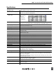
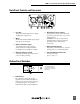
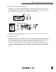
Back Panel Controls and Connectors
1
2
6
3
4
75
1) Line Out
Transformer-balanced line-level output.
+22dBupeakoutputlevel.
2) Mic In
Transformer-balancedXLRinputaccepts
microphone level signals.
3) Balanced Monitor Input
Active-balanced¼-inchconnector
accepts balanced or unbalanced line
levelsignalsfrom-10dButo+24dBu.
4) Phantom Voltage Switch
Selectsphantomvoltagesbetween48V
or12Vformicpowering.
5) Microphone Power Switch
Three-position switch selects Phantom
power,T-power(12Volts),ornopower
(DYN position).
WARNING:DonotuseT-powering
with phantom powered or dynamic
microphones(see“Microphone
Powering”).
6) Battery Compartment
RequirestwoAAbatteriesforoperation.
Insertpositive(+)endofbatteryrst
7) External DC Input Connector
Accepts5–17VDC,
pin(+),sleeve(–)..
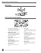
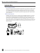
Bottom Panel Switches
1
The bottom panel switches are
accessible when the belt clip is
removed. Use a 1/16-inch allen-
head wrench.
1) DIP Switches
The“SplitEar”settingallowsthea
signal to be sent to the left headphone
earpiece and a monitor signal to be sent
totherightearpiece.Also,S2-Bcan
mute the mic audio to the headphones.