
User Manual

MM-1 User Guide and Technical Information
6
Features and specifications are subject to change. Visit www.sounddevices.com for the latest documentation.
Operational Notes
Transformers
The isolation characteristics of transformers are superior to any other balancing technique,
particularly for the adverse and uncontrolled environments of field production. Transformers
provide galvanic isolation from the driving source, meaning there is no direct electrical connection.
Signalsare“transformed”magnetically.BothtransformersintheMM-1usepremiummagneticcore
material to achieve high signal handling capability (especially at low frequencies) while keeping
distortiontoaminimum.Becauseoftheirinherentlyhighcommonmodeimpedance,transformers
are unrivaled by any other type of input for common-mode noise rejection.
BoththemicrophoneinputandlineoutputoftheMM-1canbebalancedorunbalancedwithout
problems. When unbalancing (either input or output) ground pin 3 to pin 1. There is no change in
gain with an unbalanced connection into or out of the MM-1.
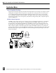
Microphone Powering
Microphonesrequiringphantompowershouldusethelowestvoltageacceptabletomaximize
batterylife.Mostelectret-condensermicrophonescanoperateonphantomvoltagesfrom11-52volts.
Thereistypicallynoperformancebenettousing48-volt;therefore12-voltphantomisappropriate.
Somemicrophoneswhichrequire48-voltphantomwillnotoperate,ormayoperatewithlower
headroomandincreaseddistortionat12volts;thereforeuse48-voltphantom.Consultyour
microphone documentation for the appropriate voltage.
Dynamicmicrophonesdonotrequirephantompower.Aproperlyconnectedbalanced,dynamic
microphone will not be affected by the presence of phantom power nor will it draw any current.
However, it is good practice to turn phantom power off if the microphone cable is suspect. Poor or
incorrectly wired microphone cable can cause audible artifacts in the microphone signal. (Phantom is
an excellent cable tester.)
T-powering is a specific powering topology needed only for T-powered microphones. T-power
electricallyis12voltsappliedtopin2withrespecttopin3oftheXLRconnector.Becauseofthe
voltage differential of T-power, it is incompatible with dynamic or phantom powered microphones
and can permanently damage dynamic and phantom powered mics.
High-Pass Filter
The two positions of the high-pass filter (low-cut) in the MM-1 are useful for removing excess low
frequencyenergyintheaudiosignals.The80Hzpositionisappropriatewhenrecordinggeneral
speech,music,andambientsound.The160Hzpositionisusefultoenhancespeechclarity.Thehigh
passlterisasinglepoledesign,6dBperoctave.
Whenpossible,attempttoequalizeatthesoundsourcewithmicrophoneselection,useofa
windscreen,microphoneplacement,andonboardmicrophoneltering.Ahigh-passlteronthe
microphone and a high-pass filter on the MM-1 will give an additive effect, increasing the slope of
the filter.
Limiter
The MM-1 has a built-in peak responding limiter which can be turned on or off by the front panel
switch. The MM-1 limiter is two separate limiters circuits activated by the one switch; the first limiter
keepstheinputgainstagefromclipping,andthesecondlimiterlimitstheoutputto+17dBu.The
twolimitersenabletheMM-1tolimitinexcessof50dB,meaningthatitisverydifculttoclipthe
unit,nomatterthegainsetting.TheLimiterLEDonthefrontpanelilluminatesamberinproportion
to the amount of limiting.