PREMIUM PORTABLE MIXER-RECORDER PRELIMINARY USER GUIDE
Legal Notices Product specifications and features are subject to change without prior notification. Copyright© 2019 Sound Devices, LLC. All rights reserved. This product is subject to the terms and conditions of a software license agreement provided with the product, and may be used in accordance with the license agreement. This document is protected under copyright law. An authorized licensee of this product may reproduce this publication for the licensee’s own personal use.
Dear Sound Professionals, Thank you very much for your interest and purchase of the Scorpio. We at Sound Devices are extremely proud of this product. We consider the Scorpio our best yet, from every aspect. We also want to thank you for your direct contribution to this product’s success. Countless conversations were shared with industry professionals regarding workflows, frustrations, wants, and needs. The knowledge obtained from these conversations drove the design and engineering of the Scorpio.
Table of Contents PANEL VIEWS 3 FRONT PANEL 3 LEFT SIDE PANEL 4 RIGHT SIDE PANEL 5 REAR SIDE PANEL 6 TOP PANEL 6 HOME SCREEN 7 CHANNEL SCREEN 8 MENUS 10 POWER MENU 11 BUS MENU 12 OUTPUT MENU 13 DANTE OUTPUT ROUTING 13 SLATE/COMS/RETURNS 17 FILES MENU 18 FRONT PANEL SHORTCUTS 22 SPECIFICATIONS 24 GLOSSARY 27 Scorpio Preliminary User Guide 2
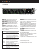
Panel Views FRONT PANEL Channel Trim Channel Fader Channel Ring LED Meter Button PFL Switch LCD Display Transport Control Power Switch/LED Indicator Menu Button Headphone Encoder Select Encoder CHANNEL TRIM Turns the channel on/off and sets the input sensitivity for the channel. To conserve power, turn off unused channels by rotating channel trim fully counter-clockwise. CHANNEL LED RING Provides visual indication of channel signal condition, solo and mute, and whether a channel is on or off.
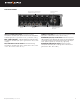
LEFT SIDE PANEL Headphone/(X9/X10) 3.5mm jack Mic/Line Inputs 1-6 female XLR jacks AES3/AES42 on XLR Inputs 1 and 6 Mic/Line Inputs 7-8 TA3 jacks Mic/Line Inputs 9-16 TA5 jacks INPUTS 1-6 FEMALE XLR JACKS Active-balanced analog microphone or line-level inputs. Inputs 1 and 6 can also accept AES3 or AES42 signal. [Pin-1 = ground, Pin-2 = hot (+), and Pin-3 = cold (-)] Com Rtn 1 TA3 jack Headphone/ Headset/External Slate Mic TA5 jack COM RTN 1 TA3 JACK Balanced connection for Com Return 1 audio input.
RIGHT SIDE PANEL Antenna SMA connector LTC/Wordclock/5-pin X1-X6 LEMO jack TA3 jacks Com Rtn 2 3.5 mm jack L,R,Rtn A (AES 5-8) 10 Pin jack X7/X8 3.5 mm jack ANTENNA SMA CONNECTOR Connects to inducted external antenna for Bluetooth LE. SD 1 AND 2 CARD SLOTS Insert SD card media for recording. Insert label side down. L,R,RTN A (AES 5-8) AND C 10 PIN JACKS Each connection includes a pair of outputs and a stereo unbalanced return input.
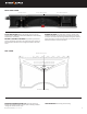
REAR SIDE PANEL 10-18 V DC 2 TA4 Jack Battery 1, Battery 2 Docking 10-18V DC2 TA4 JACK Accepts DC voltages from 10–18 V for powering. [Pin1- GND, Pin2- Smart Battery DATA, Pin3- Smart Battery CLOCK, Pin4- +10-18 VDC] BATTERY 1, BATTERY 2 DOCKING Sony L-Mount type batteries may be used. When connected to an external DC source via DC1 or DC2 the L-Mount batteries can be charged if enabled in the Power menu.
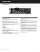
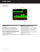
Screen Views HOME SCREEN Current take name Media space remaining indicators Individual channel meters LR mix bus meters Selected headphone preset File elapsed time Timecode Current frame rate CURRENT TAKE NAME Shows the filename of the currentlyselected take. SSD, SD1, SD2 Indicates the used/remaining space of each form of media. The internal SSD drive has a capacity of 256 GB. LR MIX BUS METERS WITH ARM/DISARM INDICATION Indicates the peak and VU audio levels of the L/R mix.
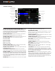
CHANNEL SCREEN Channel desgination and user-defined name Channel Meter view Channel Trim value Channel Fader Value Channel to ISO routing Channel Input selection Chanel Linking Channel EQ HPF (High Pass Filter) Polarity Channel delay Bus 1 send Limiter Bus 2 send Slate Mic Channel Mute L C R pan select CHANNEL DESIGNATION AND USER-DEFINED NAME Indicates the mixer channel designation and the user-defined name. Both are overlaid onto the channel audio meter.
Virtual Keyboard Action Function Rotate HP Scrolls orange highlight through the keyboard characters. Press HP Inserts the highlighted character in text field ‘abc’ switch Quick flick toggles between A-Z and a-z in keyboard Hold ‘abc’ switch Momentary selection of other case. Delete Deletes character to the left of flashing cursor. Hold Delete Repeatedly deletes characters to the left of flashing cursor. Space Inserts space at the flashing cursor position.
Menus MAIN MENU Scorpio Preliminary User Guide 10
Power Allows configuration of various power settings. POWER SOURCE ICONS “Batt1, Batt2, DC1, DC2, TC Batt, SL-6 DC, SL-6 NP1” Indicates the power condition of each of the power sources. Green = normal, Yellow = below normal, Orange = low Red = warning 1. PRIMARY SOURCE Selects the primary source for powering the unit. [DC 1,2* or Batt 1,2] 2. DC1 REF Allows proper power level indicator calibration based upon the type of DC power source used.
Buses Selects routing for Buses L,R and 1-10. 1. BUS METER Audio level meter for the selected bus. 2. LINK *-* Selects linking for two even to odd numbered adjacent buses. Links bus Gain, Mute Coms, and Mute All functions. 3. ISO Any ISO channel contributes to Bus mix. Green fill in text box = Pre-fade, Orange fill in text box = Post-fade, Blue fill in text box = Send (eg. Bus routing screen with Channel 1 box with blue fill = Channel 1 sending to Bus 1 via Aux 1 send) [1-32]. Bus Meter Link Iso 4.
Outputs 1. LR, X1-X10 Output Routing Selects routing for L,R and X1-X10 outputs [L Out, R Out, X1, X2, X3, X4, X5, X6, X7, X8, X9 and X10 Out] *Only a single source can be routed to an Output. If multiple sources need to be routed, use a Bus* Link A. ISO Selected source will contribute to the Output. Green = Prefade, Orange = Post-fade. [1-32] B. BUS [L,R, 1-10, HP-L, HP-R] A1 C. COM [Send 1, Send 2, RTN 1, RTN 2] D. RETURN COM [A1, A2, B1, B2, C1, C2] E.
5. HP Presets Selects the list of headphone presets available and allows for editing and creation. Function Description Name Displays virtual keyboard and allows for naming of the headphone preset. Edit Allows selection of routed sources to both HP Left and HP Right. Select HP LEFT or RIGHT and then select desired source. i. Iso- Any source selected will be routed to the selected HP output. Green = Pre-fade, Orange = Post-fade. [1-32] ii. Bus- [L,R, 1-10] iii.
Meters Selected Preset METER PRESETS 1-12 A. PEAK HOLD TIME Selects the peak hold time for the meter preset. [Off, 1*-5s., Infinity] B. METER RANGE Selects the range of the meters from bottom to top of scale. [50 dB*, 40 dB, 20 dB] C. METER VIEW Selects the meters to be viewed in the current preset. [LR,1-8, LR,9-16, LR,17-24, LR,25-32, LR,1-16, LR,17-32, LR,1-12, LR,13-24, LR,1-32, LR,Outputs, LR,Buses, LR,Returns] D. TRACK NAMES Selects display of track name in meters. [Enabled*, Disabled] E.
Record/Play SAMPLE RATE Selects the current sample rate. [44100, 47952, 48000*, 48048, 96000, 192000] BIT DEPTH Selects the current bit depth. [16, 24*] PRE-ROLL TIME Selects the amount of Pre-roll recording. Adjustable in 1 second increments. 2 s is the factory default setting. [0-5 s.] POST-ROLL TIME Selects the amount of Post-roll recording. Adjustable in 1 second increments. [0-10 s.] If a recording is stopped prematurely, press record within the post-roll time.
Slate/Coms/Returns SLATE/COM MIC SOURCE Selects the slate and com mic source. [Off, Int Mic*, Ext Mic, Ext 12 V Mic] SLATE/COM MIC GAIN Selects the gain for the slate/com mic. [020 dB in 1 dB steps for the internal mic, 0-60 dB in 1 dB steps for the external mic]. SLATE ROUTING Selects the destination(s) for the slate mic. a. Track- [1-32] b. Output- [L,R, X1-X10] c. Bus- [L,R, 1-10] [Mute Program, Unmute Program, Duck Program] d. HP- [HP-L, HP-R] [Mute Program, Unmute Program, Duck Program] e.
Files USB FILE TRANSFER Enters USB file transfer mode. Files may be transferred between a Mac or PC and Scorpio via USB-C port. *Note: when in USB file transfer mode, all other audio playback and record functions are suspended. TAKE LIST Enters the Take List. The Take List shows a running list of recorded takes in chronological order, most recent at the top. Various details of each take are indicated on the right side of the display: TC (timecode), Duration, Media, Folder, Scene, Take, Date and Notes.
SL-6 *Note: The SL-6 menu is only available when an SL-6 is connected. Power must be connected to the SL-6 via the SL-6 power connections for use with Scorpio. RECEIVER OVERVIEW Information including RF level, Transmitter battery level, channel frequency, and audio level. RECEIVER SLOT POWER Selects powering on and off of each SL-6 receiver slot. ANTENNA A POWER (BIAS) Selects 12 VDC power for active antenna use. ANTENNA B POWER (BIAS) Selects 12 VDC power for active antenna use.
System TONE SETUP Selects the level, frequency, and routing of the internal tone generator. a. Level- Selects the level of the tone generator from -20 - 0 dBFS in 1 dB increments. [-20 - 0 dBFS] b. Frequency- Selects the frequency of the tone from 100 to 10 kHz in 10 Hz steps. [100-10 kHz] c. Track- [1-32] d. Output- [L,R, X1-X10] e. Bus- [L,R, 1-10] [L-ident] NOTIFICATION BELLS Selects settings for the notification bells. a. To HP- Routes notification bell tones to the headphones. [HP-L, HP-R] b.
Quick Setup LOAD GLOBAL SETTINGS Selects a saved settings file for loading. [User-saved Global settings] SAVE GLOBAL SETTINGS Saves Global settings to various destinations. [SSD Drive (internal), INT1-4 (internal), SD1 and SD2] LOAD FACTORY SETTINGS Selects factory settings to be loaded for entire unit.
Front Panel Shortcuts quick = quickly flick toggle for < 0.
Scorpio is capable of connecting to a Dante network, receiving and sending up to 32 channels of audio simultaneously at sample rates from 44.1 kHz up to 96 kHz and 16 channels at 192 kHz. Scorpio channels 1-16 may be sourced from Dante receive channels 1-16. Scorpio channels 17-32 may be sourced from Dante receive channels 17-32. Each Dante input may be selected as a source in the channel setup menu. Each Dante output may be sourced from Isos (pre- or post-fader), Buses, and Outputs (post-delay).
Specifications Specifications are subject to change without prior notice. For the latest information available on all Sound Devices products, visit our website: www.sounddevices.com. FREQUENCY RESPONE 10 Hz to 80 kHz ± 0.5 dB (192 kHz sample rate, re 1 kHz) THD + NOISE 0.
TIMECODE AND SYNC Modes Supported: Off, Rec Run, Free Run, 24h Run, External, including External Auto-Record and Continuous modes. Frame Rates: 23.98, 24, 25, 29.97 DF, 29.97 ND, 30 DF, 30 ND Sample/Timecode Accuracy: 0.1 ppm (0.25 frames per 24 hours) Timecode Input: 20k ohm impedance, 0.3 V - 3.
FCC & ISED Compliance Statements This device complies with part 15 of the FCC Rules. Operation is subject to the following two conditions: (1) This device may not cause harmful interference, and (2) this device must accept any interference received, including interference that may cause undesired operation. Changes or modifications not expressly approved by the manufacturer could void the user’s authority to operate the equipment.
Glossary Signal Path I/O Connectors input The physical connection and associated signal type from external sources connected to a device. Inputs can include microphone inputs on XLR connectors, Dante inputs on audio-over-Ethernet, and USB audio inputs from a computer. Depending on the architecture of the mixing console its inputs may be hardwired to channels or channels can be selected from different inputs. XLR male Industry-standard 3-pin locking audio connector for microphone and line-level sources.
phantom power Condenser (capacitor) microphones require power for operation. They use power to charge the diaphragm backplate (for true condensers) and power the impedance convert located adjacent to the microphone capsule. Phantom power is the method for microphone inputs to supply DC power to the microphone through the same connection used for the audio signals from the microphone.
pan When a channel is routed to a stereo-linked bus the level it appears at each bus is adjusted by a pan control. A channel with its pan control “straight up the center”, or “centered” sends signal at the same level to each bus. A channel that is panned left or right sends the signal to the left or right bus, respectively. mute A mute control is a convenient on/off switch for a channel and an easy way to remove a channel from appearing in downstream buses.
output auto-mute When set, an output signal is muted when recording is stopped, restricting program audio from being sent to listeners “between takes.” isolated track A recorded track of an individual microphone or sound source. “Iso” recordings allow for post-record mixing of individual sound elements. output delay A digital delay applied at the output.
Non-categorized record bell A tone generated in headphones to alert the listener that recording has started. The bell is also produced when recording has ended with the stop button, when the recording volume is full, or when power is in a critical state. test tone See tone oscillator. timecode A numerical clock value expressed in hours:minutes:seconds:frames, ii.e. 04:59:39:05, used to synchronize cameras, video decks, and audio recorders.
This product incorporates software subject to the BSD license: Copyright 2001-2010 Georges Menie (www.menie.org) All rights reserved.Redistribution and use in source and binary forms, with or without modification, are permitted provided that the following conditions are met * Redistributions of source code must retain the above copyright notice, this list of conditions and the following disclaimer.
Post Office Box 576 E7556 State Rd. 23 and 33 Reedsburg, Wisconsin 53959 USA support@sounddevices.com +1 608.524.0625 main +1 608.524.0655 fax 800.505.0625 toll free www.sounddevices.