Manual TUBE VITALIZER Model 9530 Program-Equalizer
Tube Vitalizer Model 9530 Manual By Hermann Gier and Paul White Version 3.1 - 5/2000 The information in this document has been carefully verified and is assumed to be correct. However Sound Performance Lab (SPL) reserves the right to modify the product described in this manual at any time. Changes without notice. This document is the property of SPL and may not be copied or reproduced in any manner, in part or full without the authorisation of SPL.
Foreword ........................................................................ Thanks ............................................................................. Operation safety .......................................................... Introduction .................................................................. Connections .................................................................. 4 4 4 5 6 Applications Recording Studio .....................................................
Foreword Dear Customer, Thank you for the confidence you have shown towards SPL electronics GmbH by purchasing the SPL Tube Vitalizer. You have decided to use a tool of high performance which sets you in the position to have faster success and a better sound quality in your music productions and pre-masterings.
SPL´s Tube Vitalizer is the top-of-the-line product of the Vitalizer range. It is designed for the sound enthusiast in professional recording, mastering and cutting. The effect intensities are optimized for this delicate sound processing. Introduction The Tube Vitalizer combines the finest audio technologies: Tube technology, RC & LC-technology, transistor- and semiconductortechnology.
Connections The Tube Vitalizer is fitted with both XLR-connectors and TRS stereo jacks for balanced operation, though the jacks may be used with unbalanced connections simply by plugging in mono jack-plugs. The level difference that normally occurs when a balanced input or output is used unbalanced is automatically compensated for. Should the need arise to use the XLR connectors in an unbalanced system, pin 3 of the XLRs should be grounded. Inserting a mono jack also unbalances the XLRs.
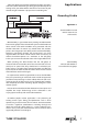
1.The most obvious application of the Tube Vitalizer is to process a final mix, either while mixing or during post-production prior to cutting. Insert your Tube Vitalizer into the master-inserts of your console or right in between a playback and a recording unit. Applications Recording Studio Application 1: The Tube Vitalizer inserted into the master-inserts of the console. More flexibility is guaranteed when patching the Tube Vitalizer into two sub-groups of the console.
Applications Application 2: The Tube Vitalizer inserted between noise-reduction and recorder to improve archived recordings. Tape Duplication Compensating indeficiencies of high-speed and real-time duplications. Broadcast Increasing the listener´s attention on jingles, promos and spots. 8 3. Tape duplication is often made at high speed resulting in a deterioration of the high frequency spectrum of the copies.
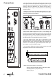
When setting up the Tube Vitalizer for the first time, it is wise to approach the controls in a specific order. Use a CD as source. The Tube Vitalizer is designed to process stereo sources. Left and right channels are adjusted with one control. First steps Set-up positions (see front panel picture): Drive to zero (center-position) Bass Sound to zero (center-position) Bass Compression to Off (counter clockwise) Hi-Mid Freq. to 3.
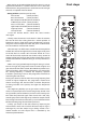
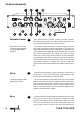
Control elements 8 11 9 16 15 10 4 2 3 1 5 Activate Process 6 1 2 10 13 14 The Activate Process function switches the Tube Vitalizer´s sound processing section on or off. The illuminated switch indicates that the Vitalizer Process has been activated. The Tube Vitalizer features a Drive control that enables you to set the level at which the Vitalizer filter network operates. The level can be changed between -20dB and +6dB.
They symbolize the contoured “Tight” bass sound. If the Bass control is moved from the center position (0) to the left, the bass sound becomes very deep, soft and warm.This sound is known as “Soft”. This is symbolized with round scaling points which also increase in size as the intensity increases.
Control elements Hi-Mid Freq. 6 The Hi-Mid Freq. control is used to set the starting frequency of a broad-band shelving filter. In line with the setting of Process Level control, all frequencies above this value right through to the end of the audio range are processed. The control range of the Hi-Mid Freq. control is between 1 kHz (extreme right) and 20 kHz (extreme left). In practice, common settings vary between 3.5 kHz and 8 kHz.
Control elements Measurement 2: Bass = Tight Bass-LC filter = Active Process Level = Max Hi-Mid Freq. = 1 / 1,5 / 2,5 / 3 / 5 / 8 / 14 / 22 kHz Measurement 3: Bass = Soft Bass-LC filter = Off Process Level = Max Hi-Mid Freq. = 1 / 1,5 / 2,5 / 3 / 5 / 8 / 14 / 22 kHz Measurement 4: Bass = Soft Bass-LC filter = Active Process Level = Max Hi-Mid Freq.
Control elements Process Level 7 The Process Level control determines the ratio between Bass and Hi-Mid Freq. to the original signal. It also determines the damping intensity of dominant mid frequencies.This allows rapid adaptation to the loudness curves (Fletcher-Munson curves, ‘curves of equal loudness’, see below). Practical adjustements range between 3 to 7. The human ear perceives the audio frequency spectrum at varying sound pressure levels very differently. Perception is by no means ‘linear’.
The Tube Vitalizer works with a filter-network and controlled changes of phase relationships to emphasize high frequencies and harmonics of the original source. The result is an unobtrusive and silky top end. Control elements 8 We consciously did without the generator principle of “Exciters”. The Tube Vitalizer’s High Freq. EQ and harmonic filter does not add any distortions to the original signal, unlike with the generator principle. It extracts all the information it needs from the original signal.
Control elements High Comp. 11 When recording on digital equipment it is essential not to overload the inputs of such systems which results in invalid samples or digital peaks. The high frequencies can contain transients or sharp s-sounds with high peak levels. The High Comp. works with a soft-knee characteristic and smoothens these peaks. We designed the compressor around the well acclaimed THAT 4301 VCA as a ‘one-knob’ solution to make it easy to operate.
When the tubes are active you can use the Attenuator controls to reduce the output level for each channel separately. Level changes due to processing can be compensated. The control characteristic has a very fine resolution before 0 dB (fully clockwise). The tube output section can be switched into a Limit mode for each channel separately. All levels exceeding 12 dB will be softly limited. Control elements 13 Attenuator 14 Atten.
Power supply Special care has gone into the design of the power supply of the Tube Vitalizer. The power supply is the heart of an electronic system: The better it is, the better the whole system works and –in an audio system– the better it sounds. Custom made toroidal transformer with five separate wirings. This power supply is based around a custom made 35 VA toroidal transformer and is designed to minimize induced hum and noise due to the non existence of an air-gap. All required voltages (230 V, 6.
Input & Output Specifications Instrumentation amplifier, electronically balanced (differential), transformerless Nominal input level ........................................ +6 dB Input impedance ............................................. = 22 kOhms Output impedance ......................................... < 600 Ohms Max. input level ................................................ +24 dBu Max. output level ............................................. +22,4 dBu Minimum load ohms .....................
Warranty SPL electronics GmbH (hereafter called SPL) products are warranted only in the country where purchased, through the authorized SPL distributor in that country, against defects in material or workmanship. The specific period of this limited warranty shall be that which is described to the original retail purchaser by the authorized SPL dealer or distributor at the time of purchase.