® User Guide v2.0 For Soundcraft Si Expression 1, 2 & 3 Incorporating Software version 1.
User Manual INFORMATION INFORMATION IMPORTANT Please read this manual carefully before using your mixer for the first time. This equipment complies with the EMC directive 2004/108/EC and LVD 2006/95/EC.
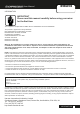
CONTENTS User Manual CONTENTS 1.0 AN INTRODUCTION TO Si EXPRESSION 1.1: Safety 1.2: Warranty 1.3: Specifications 2.0: GETTING STARTED 2.1: Console Overview 2.2: Parts Of The Console 2.3: FaderGlow 3.0: ASSIGNABLE CONTROLS 3.1: Fader Layers 3.2: Control Channels 3.2.1: Control Channel Assignment 3.3: Global Mode Encoders 3.4: Assignable Channel Strip 3.5: tOTEM (Fader Follow) 4.0: TOUCH SCREEN OPERATION 4.1: Main Menu 5.0: INPUTS & OUTPUTS 5.1: Patching 5.1.1: Soundweb Patching/Control 5.
1.0: INTRODUCTION User Manual INTRODUCTION TO EXPRESSION The Soundcraft Si Expression is a compact digital console optimised for live sound. It is designed to be powerful, yet simple to use, with intuitive controls, consistent colour-coded feedback, and rapid parameter access.
1.1: SAFETY User Manual INTRODUCTION > SAFETY SAFETY NOTICES For your own safety and to avoid invalidation of the warranty please read this section carefully. Important Symbols Cautions Alerts the user to the presence of important operating and maintenance (servicing) instructions in the literature accompanying the appliance.
User Manual 1.1: SAFETY INTRODUCTION > SAFETY WARNINGS • Read these instructions. • Keep these instructions. • Heed all warnings. • Follow all instructions. • Clean the apparatus only with a dry cloth. • Do not install near any heat sources such as radiators, heat resistors, stoves, or other apparatus (including amplifiers) that produce heat. • Do not block any ventilation openings. Install in accordance with the manufacturer’s instructions. • Do not use this apparatus near water.
User Manual 1.1: SAFETY INTRODUCTION > SAFETY WARNINGS ADVICE FOR THOSE WHO PUSH THE BOUNDARIES Although your new console will not output any sound until you feed it signals, it has the capability to produce sounds which, when monitored through an amplifier or headphones, can damage hearing over time. Please take care when working with your audio — if you are manipulating controls which you don’t understand (which we all do when we are learning), make sure your monitors are turned down.
1.2: WARRANTY User Manual INTRODUCTION > WARRANTY WARRANTY 1 Soundcraft is a trading division of Harman International Industries Ltd. End User means the person who first puts the equipment into regular operation. Dealer means the person other than Soundcraft (if any) from whom the End User purchased the Equipment, provided such a person is authorised for this purpose by Soundcraft or its accredited Distributor. Equipment means the equipment supplied with this manual.
User Manual 1.3: SPECIFICATIONS INTRODUCTION > SPECIFICATIONS Si EXPRESSION TYPICAL SPECIFICATIONS • Frequency Response - Mic / Line In to any Output: +/-1.5dB, 20Hz-20kHz • T.H.D. - Mic Sensitivity -30dBu < 0.01% @ 1kHz • Noise - Residual noise -86dBu - Mic Input E.I.N. 22Hz - 22kHz, Unweighted.
User Manual 2.0: GETTING STARTED GETTING STARTED - AN INTRODUCTION TO THIS MANUAL Anyone with minimal audio experience should be able to operate the Si Expression console without reading too much of this manual, though we do recommend you take the time to go through it. An excellent place to start would be the feature list on the introductory page (chapter reference 1.0), which will familiarise you with all of the main possibilities, facilities, and functions.
2.1: OVERVIEW User Manual GETTING STARTED > OVERVIEW Si Expression consoles offer an incredible amount of flexibility and ease-of-use for their relatively compact size. To achieve this, there are several assignable features it is advisable you understand before using the console for performance. Assignability The Assignable Channel Strip (ACS) and Global Mode Encoders are relatively straight forward and work in conjunction with the Select (SEL) Control Channel buttons and the Encoder Mode buttons.
User Manual 2.2: PARTS OF THE CONSOLE GETTING STARTED > PARTS OF THE CONSOLE 2.
2.2: PARTS OF THE CONSOLE User Manual INTRODUCTION > PARTS OF THE CONSOLE 2.
User Manual 2.3: FADERGLOW GETTING STARTED > FADERGLOW Soundcraft FaderGlow™ (Pat. Pend.) is a unique feature that gives the user an additional level of status indication, and can significantly reduce operating errors. Several different functions can be assigned to the console faders, so it can be easy to lose track of which function is currently being controlled, especially when grabbing a fader in a hurry.
User Manual 3.0 ASSIGNABLE CONTROLS ASSIGNABLE CONTROLS At the heart of the Expression is a group of assignable controls that make the console easier and faster to navigate and operate. Assignable controls work by changing the function of sections of the console surface. In this way, a single control can do several jobs, depending on the mode the console is working in.
3.1 FADER LAYERS User Manual ASSIGNABLE CONTROLS > FADER LAYERS The are four main Fader Layers on the Expression console, selected by the FADERS button (A, B, C, and D) group to the right of the Control Channels. The additional buttons in this group assign Graphic EQ bands across the faders for convenient control. Each layer is made up of a number of Control Channel assignments.
User Manual 3.2 CONTROL CHANNELS ASSIGNABLE CONTROLS > CONTROL CHANNELS A Control Channel is an assignable Channel Strip for DSP Channels, with Encoder, Fader, indicators, plus ON, SOLO, and SEL buttons. The SEL button is used to focus the Assignable Channel Strip (ACS) on that channel. The DSP channel controlled by a Control Channel is determined by the current Fader Layer (FADERS button group) and assignment (FADER SETUP Touch Screen menu).
User Manual 3.2.1 CONTROL CHANNEL ASSIGNMENT CONTROL CHANNELS > ASSIGNMENT Control Channel Assignment is accessed via the FADER SETUP button in the Touch Screen Main Menu. Select the Control channel using the Fader Layer and SEL buttons in the usual way - the current Fader Bank and Slot Number cannot be edited in the FADER SETUP menu.
User Manual 3.2.1 CONTROL CHANNEL ASSIGNMENT CONTROL CHANNELS > ASSIGNMENT Assign Stereo Inputs Assign a Stereo Input channel to the currently selected Control Channel. Touching the value field will bring up a scrollable list of available Stereo Input Channel names. Assign Mixes Assign a MIX Master channel to the currently selected Control Channel. Touching the value field will bring up a scrollable list of available MIX Master Channel names.
User Manual 3.3 GLOBAL ENCODER MODE ASSIGNABLE CONTROLS > GLOBAL ENCODER MODE Global Mode - Control Channel Encoders The encoders at the tops of the control channels can be switched globally between three different functions - GAIN/TRIM, FILT (HPF adjust), and PAN - simply by pressing the corresponding Global Encoder Mode button. The Global Encoder Mode button group is situation on the right-hand end of the console, above the LR and M Main Mix Control Channels. 3.
User Manual 3.4 ASSIGNABLE CHANNEL STRIP ASSIGNABLE CONTROLS > ACS By pressing the SEL (Select) button on any available channel, you assign that channel’s controls to the ACS. From the ACS you can control all input, EQ, dynamics, and output functions available to the selected channel. Adjusting an ACS control will trigger the ‘Function Focus’ feature and the console Touch Screen will reflect any changes you make in greater detail, as you make them.
User Manual 3.5 tOTEM (FADER FOLLOW) ASSIGNABLE CONTROLS > tOTEM (FADER FOLLOW) tOTEM (The One Touch Easy Mix) buttons MIX 1-14, MTX 1-4, FX 1-4, situated just below the ACS, make up the FADER FOLLOW button group and allow rapid access to bus contributions from channels in any current Fader Layer.
User Manual 4.0: TOUCH SCREEN TOUCH SCREEN The console colour Touch Screen can be used through direct touch, or in conjunction with the Scroll Encoder and the MENU / APPLY buttons. It provides access to System settings and preferences, Copy/Paste and cuelist / Show functionality, as well as settings for inputs, outputs monitoring, the solo system, plus a frequency response-type display of the 4-band EQ. MENU Access the Touch Screen Main Menu. Encoder Scroll or adjust parameters, and select value fields.
4.1: MAIN MENU User Manual TOUCH SCREEN > MAIN MENU The Touch Screen Main Menu can be accessed at any time by pressing the MENU button next to the Touch Screen. From here you can navigate to any of the settings menus. SHOW Show File operations and global Isolate settings, plus the RESET CONFIG function. New show, load, reset functions for show files. Isolate settings are used to isolate parameters from show recalls. See section 9.1 - Show Storage and recall - for more detail.
4.1: MAIN MENU User Manual TOUCH SCREEN > MAIN MENU SYSTEM System information, HiQnet and IP addressing, selective console reset functions, and the Event Log. Use the system menu to reset channels, busses, patching, and the whole console. See section 11.2 for more detail. PREFS Brightness settings and D.O.G.S. system (Direct Out Gain Stabiliser) On/Off. When enabled, D.O.G.S. Adjusts the direct output level from each channel inversely to any manual change of a mic gain control. See section 11.
4.1: MAIN MENU User Manual TOUCH SCREEN > MAIN MENU OSC Settings and operations for the built in Oscillator. Routing, waveform, frequency, and output options. See section 13 for more detail. MONITOR Settings for the monitoring systems. Delay, patching, and Mono Check. See section 8.5 for more information. INPUTS Input channel-specific settings. Active when an Input channel is selected. For The menu will show Naming, patching, Channel Isolate, Mix contribution routing, and so on. See section 6.1.
User Manual 5.0: INPUTS & OUTPUTS INPUTS AND OUTPUTS The console has an assignable patching system for all inputs and outputs. In other words, any internal audio signal input or output can be assigned a physical input or output. At its simplest, this might mean that the input to Channel 1 is patched to MIC01 (the first local mic/line XLR socket).
User Manual 5.1: PATCHING INPUTS AND OUTPUTS > PATCHING When patching an input or output, you will be presented with an I/O selection screen. The current patch is shown with an orange tick over the relevant patch icon. Scroll left or right through the available options and select from the labelled patch icons. The system will only show option cards if they are fitted, or if the show was created on a console with expansion cards fitted, or if the show was created with option cards in the offline editor.
5.1: PATCHING User Manual INPUTS AND OUTPUTS > PATCHING Patching for the various inputs and outputs on the console can be accessed as follows: Input Patch Source for an Input Channel. Input Channel selected > INPUTS menu. Direct Output Patch Direct output from an Input Channel. Input Channel selected > INPUTS menu Also, see D.O.G.S. below. Bus Master Output Two available outputs from each Mix, Matrix, LR, or M Master Channel. Bus Master selected > OUTPUTS menu.
User Manual 5.1.1: SOUNDWEB CONTROL INPUTS AND OUTPUTS > PATCHING > SOUNDWEB With V1.6 software, Si Performer and Si Expression consoles can now control BSS Soundweb London devices’ preamp controls via Harman’s HiQnet protocol. When a digital audio transport card (i.e. Dante, BLU Link, Cobranet, etc.
User Manual 5.1.1: SOUNDWEB CONTROL INPUTS AND OUTPUTS > PATCHING > SOUNDWEB External Control Status. Disable / Enable Soundweb London Preamp control for this patch. If enabled, this will activate MIC GAIN* and 48V control from the console on that input channel for the associated Soundweb London device. If Disabled, it will deactivate the MIC GAIN and 48V control from the console, but will keep all the settings (Node Address, Input Card, Input Channel) and the last set gain value.
5.2: DEFAULT PATCHING User Manual INPUTS AND OUTPUTS > DEFAULT PATCHING The default patching for Expression consoles - also shows default Fader Layers in brackets. The console patching can be reset to default via the SYSTEM menu. Inputs Expression 1 • Mic In 1-14 > Input Channels 1-14 (Fader Layer A, slots 1-14). • Mic In 15-16 > Input Channels 15-16 (Fader Layer B, slots 1-2). • Unassigned inputs x 6 > Input Channels 17-22 (Fader Layer B, slots 3-8).
User Manual 5.3: ViSi CONNECT INPUTS AND OUTPUTS > ViSi CONNECT The ViSi Connect card slot on the back of the console offers a 128 channel (64-in / 64-out) interface for the connection of additional inputs and outputs. There are a variety of available modules, including a MADI card that an be used to add a Soundcraft Stagebox for expanded I/O capabilities.
User Manual 5.3.1: ViSI CONNECT CARDS INPUTS AND OUTPUTS > ViSi CONNECT > CARDS Single Port CAT5 MADI Dual Port CAT5 MADI (redundant link) Dual Port Multi-Mode SC Optical MADI (redundant link) AES 3 XLR (4ch in, 4ch out on XLRs) AES D-Type (8ch in, 8ch out, 25-way D-SUB connector) Multi Digital Card (32 in / 32 out - FireWire for Mac, USB or FireWire for PC, plus 8 in / 8 out ADAT optical). Dante (64 x 64 interface to Dante digital audio network) Riedel RockNet 5.3.
User Manual 5.3.1: ViSI CONNECT CARDS INPUTS AND OUTPUTS > ViSi CONNECT > CARDS BLU Link (32 x 32 interface to Soundweb London digital audio bus) Aviom® A-Net (16 output channels, CAT5 - Pro-16 head) CobraNet™ (Up to 32 in and 32 out) MADI-USB (32 in/out MADI + 32 in/out USB OR 64 in/out MADI only. Connect Soundcraft Stagebox plus a PC or Mac. 5.3.
User Manual 5.3.2: STAGEBOXES INPUTS AND OUTPUTS > ViSi CONNECT > STAGEBOXES With a MADI card fitted, the Si Expression can be connected to A variety of additional I/O, including the Soundcraft Stageboxes. Soundcraft Mini Stagebox Two variations of a smaller Stagebox for general use when modular I/O is not required.
User Manual 6.0: CHANNELS & BUSSES CHANNELS & BUSSES The Si Expression console has several basic channels and busses. These are mono and stereo input channels, mono and stereo Mix Busses and MIX output master channels (MIX 1-14), internal FX send mix busses (FX 1-4), stereo Matrix mix busses and Matrix output master channels (MTX 1-4), and the main Left, Right, and Mono/Centre mix master channels. 6.
6.1: INPUT CHANNELS User Manual CHANNELS & BUSSES > INPUT CHANNELS Input channels receive either external input from instruments, microphones, and so on, or they receive input from the internal Lexicon FX units - in which case they are an FX return. Input channels can be mono (56 available: CH 01 - CH 56), stereo (6 available: ST 1 - ST 6), or mono-linked (assigned in odd/even pairs of mono Input Channels), and can be patched to any microphone, line, or digital input.
6.1: INPUT CHANNELS User Manual CHANNELS & BUSSES > INPUT CHANNELS 6.
User Manual 6.1.1: INPUT SETUP CHANNELS & BUSSES > INPUT CHANNELS > SETUP There are various input-specific options, found via the Touch Screen Main Menu INPUTS button. These offer channel naming, linking, Pre/Post routing options for Mix Busses and Direct Outputs, and physical input and Direct Output patching. Name Name the selected input channel. When the Name field is selected, a QWERTY keyboard will appear on the Touch Screen so you can enter the desired name.
User Manual 6.1.1: INPUT SETUP CHANNELS & BUSSES > INPUT CHANNELS > SETUP DirectOut Pre/Post Choose whether the Direct Output patch is sourced Pre Filter or Post Filter. Post Filter is immediately after the HPF (High Pass Filter) but before the main EQ and Dynamics processing stages. Pre Filter is immediately after the Analogue To Digital conversion, before the Trim, Phase, and Delay stages. Input Patch Choose a physical input for this input channel.
User Manual 6.2: MIX OUTPUTS CHANNELS & BUSSES > MIX OUTPUTS All contributions to a Mix Bus are summed into Mix Bus Master DSP Channels (MIX 1-14). They have various uses, including feeding auxiliary effects, as monitoring mixes, or creating unique mixes for zoned areas, contribution to the main mix, and more. They can be mono (MIX 1-14) or stereo (MIX 9 -14) and they receive input from the each of the MIX 1-14 busses.
User Manual 6.2: MIX OUTPUTS CHANNELS & BUSSES > MIX OUTPUTS 6.
User Manual 6.2.1: MIX OUTPUTS SETUP CHANNELS & BUSSES > MIX OUTPUTS > SETUP There are various Mix Output-specific options, found via the Touch Screen Main Menu OUTPUTS & DMX button (when an Output Channel is selected). These offer channel naming, isolate, Pre/Post routing options, width (stereo/mono) and physical output patching. Name Name the selected Mix Bus. When the Name field is selected, a QWERTY keyboard will appear on the Touch Screen so you can enter the desired name.
User Manual 6.2.1: MIX OUTPUTS SETUP CHANNELS & BUSSES > MIX OUTPUTS > SETUP Set Mix Sends Pre/Post Set all contributions to the Mix Bus Pre- or Post-Fade. This setting can override settings made in the Input Channel Setup. Pre Fader Source Select which Pre-Fader tap/source is used to supply this Mix Bus. Only relevant when a Pre-Fade routing is selected in the Input or Output Bus Setup menus. The choices (since console software version 1.6 either Pre Dynamics or Post EQ (but still pre-mute).
6.3: MATRIX OUTPUTS User Manual CHANNELS & BUSSES > MATRIX OUTPUTS The Matrix busses feed the Matrix Master channels. Matrix Busses can be used for many things, including a convenient way to send the same Mix to several monitor destinations at differing levels; or to use as an alternative main mix of mix groups to feed additional front of house zones.
6.3: MATRIX OUTPUTS User Manual CHANNELS & BUSSES > MATRIX OUTPUTS 6.
User Manual 6.3.1: MATRIX OUTPUTS SETUP CHANNELS & BUSSES > MATRIX OUTS > SETUP There are various Matrix output-specific options, found via the Touch Screen Main Menu OUTPUTS button. These offer naming, isolate, width, and physical output patching. Name Name the selected Matrix Bus. When the Name field is selected, a QWERTY keyboard will appear on the Touch Screen so you can enter the desired name. Isolate Isolate the Matrix Master DSP Channel from automation playback.
6.4: MAIN MIX OUT User Manual CHANNELS & BUSSES > MAIN MIX OUTPUTS The Main Left, Right, and Mono/Centre (L/R & M/C) busses and master channels are used for the main mix output and receive their inputs from the Input Channels and Mix Bus Master channels. The Left and Right busses feed the main Left/Right Master - a Stereo Output DSP Channel - which is permanently assigned to the Left/Right Control Channel.
User Manual 6.4.1: MAIN MIX OUTPUTS SETUP CHANNELS & BUSSES > MAIN MIX OUTS > SETUP There are various Main Left/RIght and Mono-specific options, found via the Touch Screen Main Menu OUTPUTS button. These offer naming, isolate, and physical output patching. Name Name the selected Main Output Bus. When the Name field is selected, a QWERTY keyboard will appear on the Touch Screen so you can enter the desired name. Isolate Isolate the Main Output Master DSP channel from automation playback.
User Manual 6.5: FX BUSSES CHANNELS & BUSSES > FX Busses The FX Send busses (FX 1-4) are used exclusively to feed the internal Lexicon FX units. They receive input from the Input Channels. Those contributions are accessed via the FX 1-4 tOTEM (FADER FOLLOW) buttons. Management of the Lexicon FX is done via the LEXICON button group the FX button (Lexicon FX setup). Please see section 10 for more details. 6.
User Manual 7.0: DSP ELEMENTS DSP CHANNEL ELEMENTS Input and output (Bus Master) DSP channels share many common DSP processing elements and controls via the Control Channel and Assignable Control Section (ACS). This chapter explains those elements and their controls. Please note, some elements will not be available (will be unlit and inactive) on certain channel types (Master Output Channels have no Gate section, for example). 7.
User Manual 7.1: FUNCTION FOCUS DSP ELEMENTS > FUNCTION FOCUS Function Focus allows pinpoint adjustment of any controls and settings by automatically detailing the value of both the control you are currently adjusting and any other controls in its group, plus the channel name and alternate units for the same control. For example, DELAY is illustrated in ms (milliseconds), feet, and meters, while EQ filter ‘Q’ is shown as both Q and bandwidth (octaves).
User Manual 7.2: ACS ELEMENTS DSP ELEMENTS > ACS ELEMENTS The Assignable Channel Strip (ACS) follows the currently selected DSP Channel and provides almost all of the controls relating to that. It is broken down in to small colour coded sections making it easy to identify control groups and functions at a glance.
7.2.1: ACS INPUT SECTION User Manual DSP ELEMENTS > ACS > INPUT The input section mainly provides the features required for input channels such as phantom power and mic/line level. Metering is applicable to all DSP Channel types, and HPF (High Pass Filter) is available in Auxiliary Mix master channels. Metering Signal level in channel shown as dBfs Stereo channels use both L and R bargraphs, mono channels use the L/MONO bargraph.
7.2.1: ACS INPUT SECTION User Manual DSP ELEMENTS > ACS > INPUT Phase Invert Invert signal phase (180 degrees). Pressing and holding the key will activate Interrogate mode for this function (see Mix Features 8.3). GAIN/TRIM Adjust mic gain or line trim for input channels. The control changes its function depending on the selelcted input. Mic Gain (-5dB - +58dB) is applied in the analogue domain, before analogue-to-digital conversion. It is only applicable to Microphone inputs.
7.2.2: ACS GATE SECTION User Manual DSP ELEMENTS > ACS > GATE A Gate is a threshold-driven gain reduction process normally used to attenuate a signal when its level falls below the Threshold. Setting the Threshold just above a noise floor or background noise, for example, will allow the Gate to attenuate the source during periods when the main input (voice, instrument etc) is silent. This gate includes a Sidechain Filter section.
7.2.2: ACS GATE SECTION User Manual DSP ELEMENTS > ACS > GATE DEPTH Adjust the Depth value of the Gate The amount of attenuation applied when the gate is closed. THRESHOLD Adjust the threshold of the Gate The signal level of the sidechain at which the gate is activated. S/C LPF Adjust the Sidechain Low Pass Filter This filter cuts high frequencies from the sidechain signal, limiting the frequency range of the signal that is ‘tested’ by the threshold setting.
7.2.3: ACS COMPRESSOR SECTION User Manual DSP ELEMENTS > ACS > COMPRESSOR A compressor is a threshold driven process used to reduce the dynamic range of a signal by applying gain reduction when the signal level exceeds the threshold and applying ‘make-up gain’ to keep the overall level consistent. You can use compression to increase the apparent loudness of a signal without increasing the peak level, or to control overly dynamic sources.
7.2.3: ACS COMPRESSOR SECTION User Manual DSP ELEMENTS > ACS > COMPRESSOR GAIN Adjust the make-up gain of the Compressor Gain applied after the compressor to account for level lost in compression. THRESHOLD Adjust the Threshold level of the compressor When the signal exceeds the threshold, it will be attenuated according to the ratio setting.
User Manual 7.2.4: ACS EQUALISER SECTION DSP ELEMENTS > ACS > EQUALISER The channel EQ (Equaliser) section is used for sculpting the tonal (frequency-based) balance of the signal. The expression EQ is a four-band type with two (Hi and Lo) Shelving filters, and two (Hi Mid and Lo Mid) fully parametric ‘bell’ filters. HF Level Adjust the boost/attenuation of the HF shelving filter. HF FREQ Adjust the centre frequency of the HF shelving filter.
7.2.4: ACS EQUALISER SECTION User Manual DSP ELEMENTS > ACS > EQUALISER HI MID Level Adjust the boost/attenuation of the HI MID filter. HI MID FREQ Adjust the centre frequency of the HI MID filter. Frequencies above and below this, within the bounds of the Q setting will be affected by the HI MID level control. That is, Q effectively sets the ‘width’ (bandwidth) of the filter’s bell shape and FREQ sets the frequency at the centre of the bell shape.
User Manual 7.2.4: ACS EQUALISER SECTION DSP ELEMENTS > ACS > EQUALISER LO MID Q Adjust the Q of the LO MID Filter Q is ‘magnification’ at resonance, and is inversely proportional to bandwidth. For an equaliser it is useful to think of it simply as a bandwidth control (the width of the ‘bell’ in the case of a bell-shaped filter). That is, the higher the Q, the lower the bandwidth - or the more ‘focussed’ the filter. Bandwidth (in octaves) is shown on the Touch Screen with the Function Focus feature.
User Manual 7.2.5: ACS OUTPUT SECTION DSP ELEMENTS > ACS > OUTPUT The outputs section contains features specific to the outputs of all channels. Delay and Pan (or balance) are applicable to all channel types, while LR and MONO routing is specific to input and Aux Mix master channels (not Matrix master channels). DELAY Adjust the delay applied to the output of this DSP channel. ACS units are milliseconds, though the Touch Screen will show feet and meters as well, with the Function Focus feature.
7.2.5: ACS OUTPUT SECTION User Manual DSP ELEMENTS > ACS > OUTPUT LR (Main Left Right Bus Routing) Route the selected chanel to the Main Left/Right Stereo Bus. Any channels routed to LR will be summed into the Main LR Master Output Channel, controlled by the L&R Control Channel. M (Main Mono Bus Routing) Route the selected chanel to the Main Mono Bus. Any channels routed to M will be summed (Mono) into the Main M/C Master Output Channel, controlled by the M Control Channel. 7.2.
User Manual 7.3: CONTROL CHANNEL DSP ELEMENTS > CONTROL CHANNEL Control channels contain the primary performance controls and indicators. Layers of Control Channels (assigned to various ‘actual’ channels) are selected using the FADERS (Fader Layers) button group. Control channel positions are assigned to channels using the Touch Screen FADER SETUP menu.
7.3: CONTROL CHANNEL User Manual DSP ELEMENTS > CONTROL CHANNEL Gate Closed (X) Indicates the selected channel's gate is closed. Gain Reduction Meter Indicates gain reduction for the selected channel. These are the three LEDs on the left side labelled 1, 5, 10 (dB of attentuation). Level Meter Indicates audio level for the selected channel - dBfs ON ON key function is dependant on the channel type and selected fader layer. Momentary / Latching behaviour available from software version 1.6 (see below).
7.3: CONTROL CHANNEL User Manual DSP ELEMENTS > CONTROL CHANNEL SOLO Press to Solo this DSP Channel (Input Channel, Mix Bus Master, Matrix Master). See section 8.4 for more information of the console’s Solo system. FADER Adjust signal level. Audio channel / Mix Master: Master level. FOLLOW MODE (tOTEM button selected): Send level form channel to selected bus. GEQ Mode (GEQ HI or GEQ LO FADERS button selected): GEQ band gain.
User Manual 7.4: GRAPHIC EQ (GEQ) DSP ELEMENTS > GRAPHIC EQ (GEQ) 28-Band Graphic Equalisers (GEQs) are available to all Output Masters on the console: Mix Bus, Matrix Bus, and Left/Rightand Mono Bus masters. All Output Masters can run GEQs simultaneously. When any output channel is selected, the GEQ LO and GEQ HI buttons (FADERS button group) will assign 14 bands to the Control Channel Faders, colour-coded with red FaderGlow. Faders are centre (0dB position) detented with in use as GEQ bands.
7.4: GRAPHIC EQ (GEQ) User Manual DSP ELEMENTS > GRAPHIC EQ (GEQ) When a band is moved from its zero position (0dB) the Control Channel ON button will light red to show that band is active. You can press a red ON button to ‘zero’ that band. A channel’s Graphic EQ setting does not affect the Touch Screen EQ response graphic (EQ Main Menu button). GEQ HI Press to assign the 14 'high' GEQ bands (800Hz - 16kHz) to the Control Channel Faders.
User Manual 8.0: MIX FEATURES MIX FEATURES Si Expression Mix Features include mix functions outside the normal audio signal path: Mute Groups, Copy and Paste, Interrogate, the Solo system, Monitoring, and the CLR and ALT + CLR facilities. 8.1: Mute Groups Set up groups of channels that can be muted with a single button press. You can create up to four mute groups, operated by the Mute Group Master buttons 1-4.
User Manual 8.1: MUTE GROUPS MIX FEATURES > MUTE GROUPS Mute Groups enable group-muting of selected channels at any time. Create up to four Mute Groups operated from the Mute Group Masters button group. Use the Mute Group SETUP button, a Mute Group Master button, and channel SEL buttons to set up. Mute Group SETUP Enter Mute Group SETUP mode. This mode allows you to configure Mute Group assignments in conjunction with the Mute Group Masters’ buttons 1-4. The button illuminates Red when active.
User Manual 8.1: MUTE GROUPS MIX FEATURES > MUTE GROUPS SEL Select Control Channels. While in Mute Group SETUP mode, with a Mute Group Master active, use the Control Channel SEL buttons to choose which channels should belong to that Mute Group. Orange highlighted SEL buttons indicate members of the currently selected Mute Group. CLR Clear Selection. While in Mute Group SETUP mode, holding the CLR button and pressing a Mute Group Master button will clear that Mute Group. ALT + CLR Clear all.
8.2: COPY AND PASTE User Manual MIX FEATURES > COPY AND PASTE This facility allows almost any processing section to be copied easily and quickly from a channel or bus and pasted to another channel or bus. You can also copy and paste the internal Lexicon FX settings and Aux, FX Send, and Matrix mixes. When you press COPY PASTE (Touch Screen Main Menu), or when you reselect a channel or bus while the COPY PASTE mode is active, the console’s clipboard captures the state of that selection.
User Manual 8.2: COPY AND PASTE MIX FEATURES > COPY AND PASTE DSP Channel COPY-PASTE With a DSP channel (Input Channel or Mix/Matrix Bus Master) selected, COPY PASTE mode will display a version of the ACS (with GEQ for Bus Masters). By touching sections in this Touch Screen display you can remove individual sections from the paste operation. To select a single section only, touch and hold that section in the Touch Screen.
8.3: AUDIO INTERROGATE User Manual MIX FEATURES > AUDIO INTERROGATE Audio Interrogate is a powerful method of checking and changing a particular switch status across all channels on the currently selected fader layer. For example, you can check at a glance which channels are routed to the main LR mix bus and change that status rapidly for all visible channels.
User Manual 8.4: SOLO SYSTEM MIX FEATURES > SOLO SYSTEM Solo provides a way of monitoring and checking individual channels and groups of channels quickly by routing only the ‘soloed’ channels either to the monitoring system (normal operation) or to the main mix outputs (Solo In Place - SIP). There are two main types of SOLO: PFL (Pre Fade Listen) and AFL (After Fade Listen). The difference between the two is the ‘tap’ where the solo source is taken from in the selected channel - pre- or post-fader.
User Manual 8.4: SOLO SYSTEM MIX FEATURES > SOLO SYSTEM SOLO Press to solo the assigned channel Normal button behaviour is ‘latching’ (press on - press off). Press and hold a SOLO button for momentary (non-latching) behaviour. Press and hold an active SOLO button to use the Highlight feature, which highlights a soloed channel by attenuating other soloed channels. SOLO buttons light up orange when active. SOLO CLR Press to clear any active solos. Button lights up Red to show there are active solos.
8.4: SOLO SYSTEM User Manual MIX FEATURES > SOLO SYSTEM Blend Level The attenuation level of the primary monitor source while a PFL or AFL is active. The default setting is -∞ (- infinity) resulting in complete mute of the normal monitor source. Input Priority Allow input Solos to temporarily override an output AFL. When active, this allows convenient monitor and control of contributions to a mix. If all active solos are cleared the system reverts to monitoring the active output AFL solos.
User Manual 8.5: MONITORING MIX FEATURES > MONITORING The Si Expression monitoring system is comprehensive, yet simple. The monitoring source (active monitor signal) will normally be the main LR mix, though will switch to any selection made in the Solo system - AFL or PFL busses. The active monitor signal is always available on the headphones output (located below the front of the console near fader 1) with level controlled by the MON LEVEL encoder.
8.5: MONITORING User Manual MIX FEATURES > MONITORING Monitoring Settings Menu You access the Monitor Settings menu by touching the MONITOR Touch Screen button from the Main Menu. L&R Monitor Speaker Enable / disable the Monitor Output patch. Patching for the monitor output is specified in the separate Monitor L&R OutPatch menu item below. Mono Check Outputs a mono sum of the stereo monitor signal. This adds left and right monitor outputs together.
8.6: CLR & ALT+CLR User Manual MIX FEATURES > CLR & ALT+CLR The CLR (Clear) button located to the right of the Channel Faders area is used in conjunction with individual input channels, output channels, channel parameters, and mutes to clear or reset to default. The ALT button (above-right of LRM Mix faders) can be used in conjunction with the CLR button to clear or reset parameters, channels, and bus mixes across the whole of the console.
8.6: CLR & ALT+CLR User Manual MIX FEATURES > CLR & ALT+CLR CLR + GEQ HI/LO (FADERS) Reset all Graphic EQ levels to 0dB for the currently selected channel. Only works where GEQ is available (output / bus channels). CLR + tOTEM (FADER FOLLOW) button Reset all contributions and ON status from channels or buses to the selected bus back to factory defaults. CLR + Mute Master 1-4 While in MUTE setup mode: Clear channel mute assignments to the selected Mute Master.
User Manual 8.6: CLR & ALT+CLR MIX FEATURES > CLR & ALT+CLR ALT + CLR + Any FX tOTEM button (FX 1-14) Resets all channels’ contributions to all four Lexicon FX Send busses to zero. It Does not affect the FX Send bus master channels or master levels. ALT + CLR + Any MTX tOTEM button (MTX 1-14) Resets all channels’ contributions to all four Matrix busses to zero. It Does not affect the Matrix bus master channels or master levels.
User Manual 9.0: SHOWS, CUELIST, SNAPSHOTS SHOWS, CUELIST, AND SNAPSHOTS The console file system uses the Show as it’s basic file. The Show contains all console settings, plus the Cuelist. The Cuelist contains recallable Cues that contain Snapshots of console settings, plus automation functionality - MIDI and HiQnet functionality. 9.
9.1: SHOWS User Manual SHOWS, CUELIST, SNAPSHOTS > SHOWS A Show is an entire console setup including Cuelist and associated Snapshots. Shows can be saved, loaded, and created in the EDIT SHOW Touch Screen Menu. You can also reset the I/O configuration of the console through the EDIT SHOW Touch Screen Menu. The console’s USB port allows external storage of Shows, as well as transfer between systems and the Si Expression Offline Editor software.
9.1: SHOWS User Manual SHOWS, CUELIST, SNAPSHOTS > SHOWS LOAD Initiate the Load Show process. You can navigate the internal file system (MMC) or USB key (if present) and select a Show File to load by pressing the APPLY button. The system will provide a warning that the action will overwrite the current show and allows the action to be aborted. SAVE AS Initiate the process of saving the current show. When you press SAVE, the QWERTY keyboard is shown with the current show name.
User Manual 9.2: CUELIST & SNAPSHOTS SHOWS, CUELIST > CUELIST The Si Expression incorporates a comprehensive Cuelist and snapshot automation system for fast access to preset console states and for working with other performance systems via MIDI and Harman’s HiQnet. A snapshot is a ‘picture’ of the entire console state - all settings, patching, routing, and so on.
9.2: CUELIST & SNAPSHOTS User Manual SHOWS, CUELIST > CUELIST CUE LIST Bring up the Cuelist screen in the console Touch Screen. This gives access to Cuelist editorial, and Cue editing functionality. There are four columns in the main Cuelist: Cue Number, Snapshot Name, MIDI Status, and HiQnet Status.
9.2: CUELIST & SNAPSHOTS User Manual SHOWS, CUELIST > CUELIST & SNAPSHOTS UPDATE Update the currently active Cue with the current Snapshot. Useful for editing Cues as they are used. When you press UPDATE confirmation will be required in the Touch Screen as the action will overwrite the current Cue. EDIT CUE Edit the Cue details in the Touch Screen. Includes Snapshot Name, plus MIDI and HiQnet transmit and receive settings. MOVE UP Move the currently highlighted Cue up one in the Cue List.
9.2: CUELIST & SNAPSHOTS User Manual SHOWS, CUELIST > CUELIST & SNAPSHOTS MIDI Status Highlighted blue if there is an active MIDI recieve or transmit setting in the Cue. HiQnet Status Highlighted orange if there is an active HiQnet transmit active in the Cue. 9.
9.2.1: EDIT CUE User Manual SHOWS, CUELIST > CUELIST > EDIT CUE By touching the EDIT CUE Touch Screen button in the Cue List display you access more detail, including the Cue Name, and MIDI/HiQnet automation parameters. MIDI program change messages can be used to recall Cues, and/or Cues can transmit MIDI program changes when they are recalled. HiQnet is a network protocol, developed by Harman Pro for communications and control between audio system components.
9.2.1: EDIT CUE User Manual SHOWS, CUELIST > CUELIST > EDIT CUE MIDI Receive Set the Cue to recall when the console receives a particular program change message. In the event two or more cues are set to receive the same program change on the same MIDI channel the console shall play the first cue in the CUE LIST that satisfies the condition. MIDI Program Change Turn the program change function On or Off.
User Manual 10: LEXICON FX LEXICON FX The console comes with four Lexicon FX processors, each with 29 available algorithms. Each FX unit has its own dedicated FX Send Bus, and stereo return path. Send Routing Every input channel can contribute to the FX 1-4 send busses, which correspond to the FX unit 1-4 inputs. Contributions are controlled in the same way as Mix bus contributions, via the FX 1 - 4 FADER FOLLOW (tOTEM) buttons, which assigns each channel’s contribution to the selected bus to its fader.
User Manual 10: LEXICON FX LEXICON FX Storage All Parameters from the four FX Units and for all FX Types are stored with console Snapshots. See chapter reference 9.2 for more on the Cuelist and Snapshots. Copy Paste Settings can be copied and pasted between processors using the console COPY PASTE function. Touch COPY PASTE in the Touch Screen Main Menu, then press the FX button in the Lexicon control group.
User Manual 10.1: REVERBS LEXICON FX > REVERBS Reverberation (or “reverb” for short) is the complex effect created by the way we perceive sound in an enclosed space. When sound waves encounter an object or boundary, they don’t just stop. Some of the sound is absorbed by the object, but most of the sound is reflected or is diffused. In an enclosed space, reverb is dependent on many features of that space, including the size, shape and the type of materials that line the walls.
User Manual 10.1: REVERBS LEXICON FX > REVERBS Room Reverb Room produces an excellent simulation of a very small room which is useful for dialogue and speech applications. Room is also practical when used judiciously for fattening up high energy signals like electric guitar amp recordings. Ambience Reverb Ambience is used to simulate the effect of a small or medium sized room without noticeable decay. It is often used for voice, guitar or percussion.
User Manual 10.1.1: REVERB PARAMETERS LEXICON FX > REVERBS > REVERB PARAMETERS PRE DLY - Pre Delay Adjust time delay between the source signal and the onset of reverberation. This control is not intended to precisely mimic the time delays in natural spaces, as the build-up of reverberation is gradual, and the initial time gap is usually relatively short. For the most natural effect, the Pre Delay values should be set in the range of 10-25 milliseconds.
User Manual 10.1.1: REVERB PARAMETERS LEXICON FX > REVERBS > REVERB PARAMETERS Shape Adjust the 'contour' of the reverberation envelope. With Shape all the way down, reverberation builds explosively, and decays quickly. As Shape is advanced, reverberation builds up more slowly and sustains for the time set by Spread.
User Manual 10.2: DELAYS LEXICON FX > DELAYS Delays repeat a sound a short time after it first occurs. Delay becomes echo when the output is fed back into the input (feedback). This turns a single repeat into a series of repeats, each a little softer than the last. Studio Delay The Studio Delay features up to 1 second of stereo delay and offers a built-in ducker that attenuates the delay output whenever signal is present at the input.
User Manual 10.2.1: DELAY PARAMETERS LEXICON FX > DELAYS > DELAY PARAMETERS Dly Time - Delay Time Controls the length of the delay time relative to Tempo. At the middle of its range, delay repeats are synchronous with the Tempo button; lower values create faster repeats, while higher values increase the time between repeats. Feedback Controls the number of delay repeats by feeding the delay output signal back into the delay input.
User Manual 10.2.1: DELAY PARAMETERS LEXICON FX > DELAYS > DELAY PARAMETERS Smear Ducking attenuation amount. Available only for Tape and Reverse Delays, this parameter controls the amount of “smear,” or signal degradation and frequency loss. The higher the setting, the more each delay repeat loses intelligibility compared to the original signal. Ratio - Tap Ratio Controls the Tap ratio of left and right outputs relative to the Delay time.
10.3: MISC FX User Manual LEXICON FX > MISC FX The MISC category provides primarily modulated and pitch-varying effects. Chorus Chorus creates a lush, full sound by combining two or more signals together where one is unaffected and the other signals vary in pitch very slightly over time. Chorus is commonly used to fatten up tracks and to add body to guitars without colouring the original tone. Chorus can also be used with discretion to thicken a vocal track.
User Manual 10.3.1: MISC FX PARAMETERS LEXICON FX > DELAYS > DELAY PARAMETERS Speed Sets the speed at which the modulated effect cycles. Depth - LFO Depth Scales the intensity of the effect. This control affects the output of the LFO only. It has no effect on the outputs of the individual waveforms. Voices - Number Of Voices Controls the number of additional Chorus voices. Higher amounts add more richness to the Chorus effect.
User Manual 10.3.1: MISC FX PARAMETERS LEXICON FX > DELAYS > DELAY PARAMETERS Waveform Selects the wave pattern used by the modulated effect. Select from sine wave, triangle wave, Stepped Triangle, and random. Phase Controls whether amplitude or depth change occurs in both left and right outputs simultaneously or alternates between left and right outputs. This control affects the output of the LFO only. It has no effect on the outputs of the individual waveforms.
User Manual 10.3.1: MISC FX PARAMETERS LEXICON FX > DELAYS > DELAY PARAMETERS Rot Max Sets the maximum speed at which the LF Speaker will rotate. Rotary effect only: The speed limits are used when the speed parameter is changed from Slow to Fast. Horn Min Rotary effect only: Minimum speed of the HF rotary horn. The speed limits are used when the speed parameter is changed from Slow to Fast. Horn Max Rotary effect only: Maximum speed of the HF rotary horn.
User Manual 10.3.1: MISC FX PARAMETERS LEXICON FX > DELAYS > DELAY PARAMETERS Fdbk 'n' - Feedback Adjusts how much of the shifted signal is sent back through the delay line in Pitch Shift and Detune. For creating cascading arpeggio-type effects. Pan 'n' Sets the pan position in the stereo field for each tap in the 2-Tap Delay or each channel of the pitch shift/detune effects.
User Manual 11.0: PREFERENCES, SYSTEM, SECURITY SYSTEM SETTINGS System Settings are accessed via the Touch Screen Main Menu and appear under the Menus PREFERENCES, SYSTEM, and SECURITY. 11.1: Preferences (PREFS) The PREFS Menu is mainly concerned with LED and LCD (display, buttons etc) brightness and adjustments. However, this is also where you enable or disable the D.O.G.S. (Direct Output Gain Stabiliser) mode so gain changes at mix pre-amps don’t affect the Direct Outputs levels. 11.
11.1: PREFERENCES User Manual SYSTEM SETTINGS > PREFERENCES Preferences include console brightness settings and the D.O.G.S. (Direct Out Gain Stabiliser) system enable. LED Brightness Adjust the brightness of LEDs across the console. This includes all Encoder level indicators, metering, and status LEDs. FaderGlow Brightness Adjust the FaderGlow brightness across the console. This includes all colour fader lighting. Screen Brightness Adjust the Touch Screen brightness. D.O.G.S.
11.2: SYSTEM MENU User Manual SYSTEM SETTINGS > SYSTEM MENU The System menu provides information about the console itself, as well as offering settings for the console name, date, time, wordclock, and network settings (for HiQnet and Soundweb functionality). The System Menu also provides reset functions for channels, busses, patching, and ‘all’, as well as the Event Log. RESET CHANNELS Reset all Input audio channels to factory default.
11.2: SYSTEM MENU User Manual SYSTEM SETTINGS > SYSTEM MENU RESET ALL Reset all parameters including names and patches to factory default. You will be asked to confirm this action in the Touch Screen. EVENT LOG A log of specific system events. Can be useful for trouble shooting and for technical support staff. Console Name Name the console Touch / select the value field to bring up a QWERTY keyboard to edit the Name.
11.2: SYSTEM MENU User Manual SYSTEM SETTINGS > SYSTEM MENU Time System Time. Touch or select to bring up a time editor in the Touch Screen. Wordclock Choose an Internal, External, or Option card wordclock reference. The console can be set as Word Clock Client (EXTernal or OPTION) or Master (INTernal). When set to EXTernal the console will attempt to clock from an incoming word clock to the rear panel Word Clock connection. If successful, a CLOCK icon displayed on the title bar.
User Manual 11.2: SYSTEM MENU SYSTEM SETTINGS > SYSTEM MENU HiQnet Enabled/Disabled Turn HIQnet capability On of Off. This console can transmit HiQnet Venue Events on the network along with cue recalls. Please see chapter reference 9.2 for more detail. The console can also control Soundweb London Device Pre amp devices directly via HiQnet - see chapter reference 5.1.1 for more detail. HiQnet Address The HiQnet address of this device. 11.
User Manual 11.3: SECURITY MENU SYSTEM SETTINGS > SECURITY MENU This console can be set to allow specific access privileges to a number of users. You can lock-out a variety of console functions, as defined in User Profiles. When LOCK is set in the Security menu, a user selection and valid password are required to operate the console. Access privileges are defined in the PROFILES menu. Each user is assigned a Profile when they are created.
User Manual 11.3: SECURITY MENU SYSTEM SETTINGS > SECURITY MENU DELETE USER Delete the selected User. The system will ask for confirmation in the Touch Screen to confirm this action. PROFILES Access the Profiles Menu. Use the Profiles Menu to add and edit profiles that can be assigned to users. A ‘profile’ is a set of access privileges assigned to a User (a ‘User’ is a person / administrator account). LOCK Lock the console.
User Manual 11.3.1: ADD / EDIT USER SYSTEM SETTINGS > SECURITY > ADD / EDIT USER The Add and Edit User menus require similar information - User Name, Profile, and Password. Profiles can be created and/or edited in the Edit Profile menu (see chapter reference 11.3.2 for more detail). User Name Name the User. Touching or selecting the value field brings up a QWERTY keyboard in the Touch Screen. Profile Profile Name. Select from the current range of access Profiles.
User Manual 11.3.1: ADD / EDIT USER SYSTEM SETTINGS > SECURITY > ADD / EDIT USER CANCEL Cancel the current User creation or edit without saving any altered values. SAVE Save the current User. 11.3.
User Manual 11.3.2: PROFILES SYSTEM SETTINGS > SECURITY > PROFILES A profile defines the access privileges of a console User. Many functional aspects of the console can be denied to users, according to the Profile. The access categories are: Input Processing, Bus Sends, Bus Processing, Matrix Sends, Matrix Processing, Main Output Processing, Main Output Matrix Sends, Main Output On Faders, GEQ, Fader Layer A, Fader Layer B, Fader Layer C, Fader Layer D, FX, Touch Screen, and Cue List.
User Manual 11.3.2: PROFILES SYSTEM SETTINGS > SECURITY > PROFILES CANCEL Cancel the current Profile creation or edit without saving any altered values. SAVE Save the current Profile. Profile Select a profile to view or edit. Touch or select the value field to select a Profile. You can only edit profiles when logged on as the Administrator. 11.3.
11.4: SOFTWARE UPDATE User Manual SYSTEM SETTINGS > SOFTWARE UPDATE The Si EXPRESSION software is updated via the USB port on the front panel. Details and special instructions for any release will be included with the software release package; however, the ‘normal’ procedure is listed below for reference: 1. Unzip the files to a USB key in the root directory, you should have two or three files: Expression. bin; info.xml; PerformerFader.hex (optional, see release notes). 2.
11.5: RESET CONSOLE User Manual SYSTEM SETTINGS > RESET CONSOLE The following procedure will restore the console back to the factory defaults and re-format the internal SD card. DO NOT do this if you wish to keep saved data (Shows). You can use the RESET options in the SYSTEM menu to set parameters and settings back to factory default without destroying data. Remember: All settings, cues, users, profiles and shows will be lost. 1.
User Manual 12: OSCILLATOR OSCILLATOR The console’s internal Oscillator is a signal generator provided for various test purposes. It can generate either a sine wave or pink noise (equal power per octave) and has various routing options to Mix and Matrix busses, as well as a patchable physical output. It is not possible to route directly to the console’s LR and MONO buses, though you can route the Oscillator signal to a Mix bus master then use the LR and MONO routing keys.
User Manual 12: OSCILLATOR OSCILLATOR Frequency Set the frequency for the Oscillator's Sine output. Type Set the signal type for the Oscillator output. Either Sine Wave or Pink Noise (Full spectrum, equal power per octave). Oscillator Out Patch Set a physical output for the Oscillator signal Touching or selecting the value field will bring up a normal patching screen in the Touch Screen. See Section 5.0 for more details.
User Manual APPENDIX 01: NO SOUND? NO SOUND? A Troubleshooting Guide. One of the most common problems experienced with mixing consoles is finding that an input isn’t appearing at an output. There are many possible reasons for this, but the best way to troubleshoot it is to first make sure the Control Channel is set up correctly and to go through the signal path and workout where the ‘break’ is... You can check the exact audio path of any signal by referring to the signal path diagrams in Chapter 6.
User Manual APPENDIX 01: NO SOUND? NO SOUND? Is the Gate shut? It is possible for an incorrectly set Gate process to stop all signal. This happens most often when the threshold is set too high and the signal never gets loud enough to 'open' the Gate. You can easily check this by turn the Gate process off with the GATE button in the GATE section of the ACS (7.2.2).
User Manual APPENDIX 01: NO SOUND? NO SOUND? Is the Signal Routed to a valid output bus or channel? Routing can cover LR and Mono routing, as well as Mix bus routing. This will depend on the particular instance. If the issue is no output at the main LR or mono outputs for example, then check than the signal is routed using the LR and/or MONO buttons in the ACS OUT section (7.2.5).