© Harman International Industries Ltd. 1997, 1998 All rights reserved Parts of the design of this product may be protected by worldwide patents. Part No. ZM0215 Issue 1 Soundcraft is a trading division of Harman International Industries Ltd. Information in this manual is subject to change without notice and does not represent a commitment on the part of the vendor. Soundcraft shall not be liable for loss or damage whatsoever arising from the use of information or any error contained in this manual.
B400 Contents 1. Introduction 1.1 Introduction 1.2 Warranty 1.3 2. Installation 2.1 Dimensions 2.2 Earthing the Console 2.3 Meterbridge 2.3 Rear Connector Panel EDAC Connectors 2.4 Rear Connector Panel D-type Connectors 2.6 Jumper Options 2.8 Internal Monitor Source Selection Block Diagrams 3.1 Mono Input Module 3.2 Stereo Input Module 3.3 Mono Group Module 3.4 Stereo Master Module 3.5 Communications Module 3.6 Monitor Module 3.7 Functional Description B400 Contents 2.
Specifications B400 Typical Specifications ii 5.1 5.
B400 1 B400 Introduction Introduction 1.
Introduction Congratulations on purchasing a Soundcraft console. The B400 has been designed to meet the needs of Live TV & Radio Broadcast and Production Facilities including OB vehicles. Based on the highly successful B800, the B400 delivers a level of configurability unrivalled in its class.
Power Supply l The B400 uses the CPS275 Power Supply. Warranty 1 Soundcraft is a trading division of Harman International Industries Ltd . End User means the person who first puts the equipment into regular operation. Dealer means the person other than Soundcraft (if any) from whom the End User purchased the Equipment, provided such a person is authorised for this purpose by Soundcraft or its accredited Distributor. Equipment means the equipment supplied with this manual.
1.
B400 2 B400 Installation Installation 2.
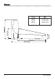
Dimensions 24-Module 32-Module 40-Module 48-Module 56-Module 2.2 833.72mm / 32.82" 1087.72mm / 42.82" 1341.72mm / 52.82" 1595.72mm / 62.82" 1849.72mm / 72.
Earthing the Console Important Notice. The console has two earth posts on the rear connector panel. They are located near to the power supply connectors. The un-insulated metal post is the chassis ground, and the insulated post is the system ground. The console is supplied with these two posts linked together. It is essential that the console is operated with these two earths linked.
Rear Connector Panel EDAC Connectors There are two female 90-way EDAC connectors on the rear connector panel. The illustration below shows the pin labelling (as viewed from the outside of the console). The pins are listed in circuits below - the circuit functions for each EDAC are shown on the following pages. CCT 1 CCT 2 CCT 3 CCT 4 CCT 5 CCT 6 CCT 7 CCT 8 CCT 9 CCT 10 CCT 11 CCT 12 CCT 13 CCT 14 CCT 15 CCT 16 CCT 17 CCT 18 CCT 19 CCT 20 CCT 21 CCT 22 CCT 23 CCT 24 2.
90-Way EDAC 1 & 2 Connectors B400 Installation EDAC 1 Circuit Number CCT 1 CCT 2 CCT 3 CCT 4 CCT 5 CCT 6 CCT 7 CCT 8 CCT 9 CCT 10 CCT 11 CCT 12 CCT 13 CCT 14 CCT15 CCT16 CCT17 CCT18 CCT19 CCT20 CCT21 CCT22 CCT 23 CCT 24 Function not used Ext Cue I/P Prod T/B I/P T/B to Ext Oscillator L Oscillator R Ext Mon I/P L Ext Mon I/P R Stud Spkr L Stud Spkr R PH1L Studio PH1R Studio T/B to opt 1 T/B to opt 2 Ext 1L Ext 1R Ext 2L Ext 2R Ext 3L Ext 3R Ext 4L Ext 4R PH2L Guest PH2R Guest EDAC 2 Circuit Number CCT 1
Rear Connector Panel D-Type Connectors There are a number of 25-way D-type female connectors (depending upon the number of input channels) on the rear connector panel. The connector layout varies with the configuration of input modules and mono and stereo input modules differ in the facilities available. l Each block of four Mono inputs has one D-type connector for external mutes, and one D-type for Mic Live Remotes.
STEREO INPUT REMOTES Pin Function 1 2 3 4 5 6 7 8 9 10 11 12 13 REMOTE START #4 (Ch 4, 8, 12 etc.) REMOTE STOP #4 (Ch 4, 8, 12 etc.) REMOTE START #4 (Ch 3, 7, 11 etc.) REMOTE STOP #4 (Ch 3, 7, 11 etc.) REMOTE START #4 (Ch 2, 6, 10 etc.) REMOTE STOP #4 (Ch 2, 6, 10 etc.) REMOTE START #4 (Ch 1, 5, 9 etc.) REMOTE STOP #4 (Ch 1, 5, 9 etc.) Not used Not used Not used Not used Not used Pin Function 14 15 16 17 18 19 20 21 22 23 24 25 REMOTE START #3 (Ch 4, 8, 12 etc.) REMOTE STOP #3 (Ch 4, 8, 12 etc.
Jumper Options * = DEFAULT MONO INPUT Audio SW19 Released = Insert Point is Pre-fade (see links 1 to 4) Depressed= Insert Point is Post-fade (links 1 to 4 have no effect, but they must be present) LK1-4 Pre-fade Insert 1-2 = Pre Eq 2-3 = Post Eq* J1,2 HF EQ 1-2 = Bell* 2-3 = Shelf J3 Meter Input 1-2 = Pre EQ 2-3 = Pre Fade* J4 Stereo Aux 4 pre fade source 1-2 = Pre mute* 2-3 = Post mute J5 Mono Aux 1-3 pre fade source 1-2 = Pre mute* 2-3 = Post mute J6 Dir O/P via Aux 1 Level pot 1-2 = Di
Logic SW21-A SW21-B SW21-C SW21-D SW21-E Closure disables dual action of Cue sw.
STEREO MASTER J1 Remote Common 1-2 = Local * 2-3 = Rem com J2 - J3 Mono Output post fade,pre limiter/post limiter 1-2 = Post limiter* 2-3 = Pre limiter J4 Talkback replaces or mixes with Program Fit = Replaces* Omit = Mixes J5, 6 Limiter Pre-emphasis Fit = On Omit = Off* MONITOR MODULE J1 Ext 8 Input Sensitivity 1-2 = +4dBu * 2-3 = -10dBV J2, 3, 4 Cue to Monitor/Talk to Studio (2 Mntr Mods.
Internal Monitor Source Selection The DESK 'A' bank of switches, on the Monitor Module, allows you to select 1 of 6 internal signals as the internal monitor source. The 6 are selected via the scramble card (SC3556) in the console. The appropriate section of this PCB's silk screen is reproduced below. The six signals may be chosen from Groups 1 to 8, the Stereo Mix (ST), a mono sum of the Stereo Mix, or Aux1 to Aux 4.
2.
B400 3 B400 Block Diagrams Block Diagrams 3.
48V PHANTOM -30dBu TONE 48V HPF GAIN LINE MIC LINE OPTION TONE EQ 3-Band, Semi-Parametric EQ * PAD HF LF MF Cut/Boost PHASE REV LINE REMOTE START LINE REMOTE STOP Centre Freq.
-30dBu TONE INPUT B (TELCO OPTION) A TONE MONO R Option TRIM LEFT INPUT DIFF B MONO L Option A DIFF RIGHT INPUT RHS PHASE B STUDIO MUTE MONITOR DIM REM COM TELCO HPF T0 PEAK DETECT CIRCUIT STUDIO MUTE REMOTE START 1 RELAY CONTROL LOGIC MONITOR DIM ON MF LF MF PAN REMOTE STOP 1 T0 PEAK DETECT CIRCUIT REM COM REMOTE START 2 LED METER CENTRE FREQ CUT BOOST BAL / PAN 3-Band EQ REMOTE STOP 2 PEAK LED CUT BOOST CUT BOOST REDIRECT - OPTION BAL / PAN EQ 3-Band EQ HF HF 2
LEVEL PAN GRP MUTE LEFT STEREO TAPE RETURN INS RIGHT Note: the Insert Point may be configured to be in an alternative place which is marked thus - CUE (St. Ret) REMOTE START GROUP MIX NOTE: the Group Mix carries one of the 8 group mixes, depending upon its position INSERT in the console.
FADER INSERT SEND ST L MIX MUTE FADER DOWN INS INSERT RETURN LIMITER IN LIMITER TO MONITOR & METERBRIDGE OUTPUT ROUTING CONTROL TRANSFORMER OPTION ST LEFT OUTPUT TALK ST1 (or ST2) TONE ST LEFT TONE ST RIGHT TONE ST CTL TB ST CTL REM COM PRE REMOTE START RELAY CONTROL LOGIC PEAK DETECT MUTE MONO OUTPUT MONO LEVEL ST R MIX (EDAC CONNECTOR) TO MONITOR & METERBRIDGE EXT MUTE FADER ON-AIR CTL INSERT SEND MUTE ST1 MASTER ONLY INS FADER DOWN POWER SUPPLY VOLTAGE MONITOR INSERT RETURN ON-AI
SLATE CTL SLATE/TALKBACK CONTROL OSCILLATOR/ SLATE OSCILLATOR OSC CAL 100 400 1k 10k SLATE FREQ HZ OSC LEVEL OSC ON OSC R -30 CAL OSC L -30dB -30dBu TONE EBU TONE ON-AIR CTL ON-AIR CTL CONTROL CIRCUIT TO INTERUPT OSC L OUTPUT TONE ST1 L TONE TO ST1 TONE ST1 R TONE ST1 CTL SLATE TALK/TONE MNTR DIM OPT 2 CTL #1 & 2 EXT CUE I/P TB TO OPT 2 CALL 2 CALL 1 TB TO OPT 1 OPT 1 CTL #1 & 2 T/B MIC L R TALK TO CLNFD T/B GAIN TB TO EXT EXT TALK BUS TB TO EXT CTL ST TALK ST TALK ST TA
AUX MONITOR FEEDS FROM ST MODULES ST MONITOR FEEDS FROM ST MODULE ST LEFT O/P ST RIGHT O/P ST MONO O/P AUX 1 AUX 2 AUX 3 AUX 4 LEFT AUX 4 RIGHT LHS SELECT 6 INPUTS SELECTED VIA THE SCRAMBLE CARD INT ’A’ SIX STEREO PAIRS SPARE MONO R RHS SELECT GROUP 1 GROUP 2 GROUP 3 GROUP 4 GROUP 5 GROUP 6 GROUP 7 GROUP 8 GROUP MONITOR FEEDS FROM GROUP MODULES EXT A/B L EXT A/B R SOURCE A/B 8 BALANCED EXTERNAL ’B’ L INPUTS RHS PHASE LHS SELECT EXT ’B’ 8 BALANCED EXTERNAL ’B’ R INPUTS MONO L RHS SELECT
3.
B400 4 B400 Functional Description Functional Description 4.
Mono Input Module +48V The 48V switch applies 48V Phantom power to the MIC I/P XLR on the rear connector panel. The switch illuminates to indicate that it is switched on. TONE The TONE switch replaces the mic/line signal with the desk oscillator, allowing you to check the operation of the module. The switch illuminates to indicate that it is switched on. Note that if the module is switched to TONE the monitor mutes and remotes (start/stop) are disabled.
MF The upper, larger knob of the MF section allows you to cut or boost the High MidRange bell-response filter by up to 15dB. The Mid-point frequency is sweepable, using the lower knob, between 250Hz and 4kHz. The Q-factor of the filter is fixed at 1.4. LF The LF knob provides 15dB cut or boost of the LF shelving filter. EQ The EQ section may be switched in and out of circuit via the EQ switch. The switch illuminates when pressed to indicate that the EQ is switched in.
When the input is in line level mode and the CUE switch is pressed, this will (optionally) trigger the remote start/stop facility which has two sets of relay contacts, available via the rear panel D-type connector. These relays can be set to either latching or pulsed operation via internal jumpers, enabling most types of machines to be remotely started and stopped. Under no circumstances should mains voltages be placed on the contacts of the remote Start/Stop relays.
Rear Connector Panel XLR-type connectors are provided for the main audio connections to the module. Pinouts are as follows: Direct Output Pin1 Pin2 Pin3 Insert Send Pin1 Pin2 Pin3 Insert Return Pin1 Pin2 Pin3 Line Input Pin1 Pin2 Pin3 Mic Input Pin1 Pin2 Pin3 B400 Functional Description Chassis Hot Cold Chassis Hot Cold Chassis Hot Cold Chassis Hot Cold Chassis Hot Cold 4.
Stereo Input/Telco Module TONE The TONE switch applies a -60dBu signal to the modules pre-amplifier circuit. This allows you to check the operation of the module. The switch illuminates to indicate that TONE is active. Note that if the module is switched to TONE the monitor mutes and remotes (start/stop) are disabled. MONO SOURCE When the L and the R switches are both released the stereo pairs of the sources are routed normally in stereo.
HPF The High-Pass Filter is switched on when the button is pressed. The switch illuminates to indicate that it is switched on. The filter has a slope of 18dB/Octave and a cut-off point of 100Hz. Equaliser - HF The Equaliser is a 3-band semi-parametric design. The HF shelving section provides 15dB cut or boost at 10kHz. MF The upper knob of the MF section allows you to cut or boost the Mid-Range bellresponse filter by up to 15dB.
When the input is in line level mode and the CUE switch is pressed, this will (optionally) trigger the remote start/stop facility which has two sets of relay contacts, available via the rear panel D-type connector. These relays can be set to either latching or pulsed operation via internal jumpers, enabling most types of machines to be remotely started and stopped. Under no circumstances should mains voltages be placed on the contacts of the remote Start/Stop relays.
Rear Connector Panel XLR-type connectors are provided for the main audio connections to the module. Pinouts are as follows: Direct Output Pin1 Pin2 Pin3 Input Pin1 Pin2 Pin3 B400 Functional Description Chassis Hot Cold Chassis Hot Cold 4.
Mono Group Module There are up to eight Mono Group Modules in the console. The module comprises a Group Master section and a Stereo Return section. Stereo Return The stereo return normally receives inputs via two XLR sockets on the rear connector panel. TAPE RTN (BUS) When the BUS switch is pressed the inputs to the stereo return section are disabled and are replaced by the local Group output signal.
Fader The Fader controls the overall Group level, with 10dB of gain in hand at the top of the fader. A set of relay contacts to start an external machine is available on the rear connector panel. These contacts close when the fader is away from the fully-down position. Under no circumstances should mains voltages be placed on these contacts.
PK The PK LED monitors pre-insert and post-fade signal levels. If either of these points rises to 6dB below clipping the LED will illuminate. SP (Signal Present) The signal present circuit monitors the output of the mix amp. The SP LED illuminates when a signal is present on the Group Mix bus. 4.
Rear Connector Panel XLR-type connectors are provided for the main audio connections to the module. Pinouts are as follows: Group Output Pin1 Pin2 Pin3 Insert Send Pin1 Pin2 Pin3 Insert Return Pin1 Pin2 Pin3 Stereo Return R Pin1 Pin2 Pin3 Stereo Return L Pin1 Pin2 Pin3 B400 Functional Description Chassis Hot Cold Chassis Hot Cold Chassis Hot Cold Chassis Hot Cold Chassis Hot Cold 4.
Stereo Group Module There are up to four Mono Group Modules in the console. The module comprises a Group Master section and a Stereo Return section. Stereo Return The stereo return normally receives inputs via two XLR sockets on the rear connector panel. TAPE RTN (BUS) When the BUS switch is pressed the inputs to the stereo return section are disabled and are replaced by the local Group output signal.
Fader The Fader controls the overall Group level, with 10dB of gain in hand at the top of the fader. A set of relay contacts to start an external machine is available on the rear connector panel. These contacts close when the fader is away from the fully-down position. Under no circumstances should mains voltages be placed on these contacts. IMAGE WIDTH The image width control allows the stereo image to be varied from Mono, through normal Stereo, to Wide Stereo.
PK The PK LED monitors pre-insert and post-fade signal levels. If either of these points rises to 6dB below clipping the LED will illuminate. SP (Signal Present) The signal present circuit monitors the output of the mix amp. The SP LED illuminates when a signal is present on the Group Mix bus. 4.
Rear Connector Panel XLR-type connectors are provided for the main audio connections to the module. Pinouts are as follows: Insert Send Pin1 Pin2 Pin3 Insert Return Pin1 Pin2 Pin3 Stereo Return R Pin1 Pin2 Pin3 Stereo Return L Pin1 Pin2 Pin3 B400 Functional Description Chassis Hot Cold Chassis Hot Cold Chassis Hot Cold Chassis Hot Cold 4.
Stereo Master Module POWER SUPPLY STATUS The three LEDs provide visual confirmation that the 48V phantom power, +17V & -17V Audio Supplies, and the +5V Logic Supply are all present. ON-AIR The ON-AIR switch,when activated, will close a set of normally-open relay contacts. It also disables the oscillator and some talkback facilities provided by the Communications Module. The On-Air switch may also be operated externally via the opto-isolated connections on the rear panel.
Mono Output The mono output may either be derived from a mono sum of the pre-mute, preinsert left and right signals, and therefore is also unaffected by the limiter, or, by changing internal jumpers, may be derived post-limiter. LEVEL The LEVEL control sets the final output level. This may be fed by a pre-fade signal or a post-fade signal (i.e. pre or post-fade the stereo master fader) by use of the associated PRE switch. MUTE The output is muted whent the MUTE switch is pressed.
Rear Connector Panel XLR-type connectors are provided for the main audio connections to the module. Pinouts are as follows: Insert Send L Pin1 Pin2 Pin3 Insert Return R Pin1 Pin2 Pin3 Insert Send R Pin1 Pin2 Pin3 Insert Return L Pin1 Pin2 Pin3 Stereo Output R Pin1 Pin2 Pin3 Stereo Output L Pin1 Pin2 Pin3 4.
Communication Module Oscillator FREQ Hz The internal oscillator may be set to one of 4 different frequencies by the FREQ switch, ranging from 100 to 10kHz ON The ON switch enables the oscillator when pressed and illuminates to indicate that the oscillator is active.
When the switch in question is released the talkback output carries, depending on link settings, either no signal or the signal from the EXT CUE contacts which are also available on the Comms Module EDAC. When the switch is pressed the appropriate output carries the console Talkback signal. Talkback T/B GAIN The input to the talkback system is from the Talkback Mic XLR which is provided as standard on the overbridge and overall gain is adjusted via the T/B GAIN control.
GUEST PHONES This control sets the level of the Guest Heaphones output. The source is selected as described in (16) above. STUDIO PHONES This control sets the level of the Studio Heaphones output. The source is selected as described in (16) above. If TALK TO STUDIO is active (see 15 above), the stereo master signal will be routed in mono to the left side of the headphones, with talkback routed to the right.
Monitor Module The Monitor Module provides facilities for mono and stereo monitoring of many internal and external sources. Monitor Sources SOURCE A/B The SOURCE A/B switch selects either the DESK A or the EXTERNAL B bank of switches as the monitor source. The switching may also be done externally via separate control lines for the left and right signals. The EXT L and EXT R LEDS illuminate when the external control is active.
H/P SPLIT If the H/P SPLIT switch is pressed, and a CUE is operated from anywhere on the console, the monitor signal (in mono, summed if it is stereo) is sent to the left side of the headphones only. The Cue signal is fed to the right side of the headphones. ALT SPKR There are two sets of monitor speakers. Monitor Speakers 1 are normally selected but Monitor Speakers 2 may be selected by pressing the ALT switch.
MASTER AFL The Cueing system may be set to monitor PFL or AFL signals from the various CUE switches on the console. This is done via the MASTER AFL switch, which selects AFL mode when pressed. AFL ADJ Note that when AFL is selected, the AFL ADJ preset is switched into operation. This preset allows you to trim the level set by the CUE MNTR LEVEL pot. CLEAR CUE The various Cue switches may be electronically latched and unlatched by toggling the individual switches.
Meterbridge Modules Meterbridge Speaker The meterbridge speaker is sourced from the Monitor Module, and has its own local volume control. Talkback Mic The talkback mic socket is routed onto the Talk Bus via the Communications Module. B400 Functional Description 4.
Meter Selector Panel This panel allows you to monitor a variety of console signals. The meters which would be used in conjunction with this panel may be chosen from a range of Soundcraft meter panels which are available from your dealer. It is suggested that a suitable choice would be a L/R pair + phase correlator.
B400 5 B400 Specifications Specifications 5.
B400 Typical Specifications Connections Mic Input (XLR) Line Input (XLR) Insert Send (XLR) Insert Return (XLR) Mono Direct Out (XLR) Stereo Direct Out (XLR) Group Insert Send (XLR) Group Insert Return (XLR) Group Output (XLR) Aux Output (XLR) Monitor Output (XLR) Main O/P Insert Send (XLR) Main O/P Insert Return (XLR) Main Output (XLR) >1.
CMRR Mic Input Line Input Mono Input Min Gain 65dB @ 50Hz 55dB @ 1kHz 50dB @ 10kHz 45dB @ 1kHz 40dB @ 10kHz Max Gain 90dB @ 50Hz 80dB @ 1kHz 60dB @ 10kHz Stereo Input 55dB @ 1kHz 50dB @ 10kHz Crosstalk Channel muting Channel fader attention 95dB @ 1kHz 90dB @ 10kHz 90dB @ 1kHz 85dB @ 10kHz 90dB @ 1kHz 85dB @ 10kHz 90dB @ 1kHz 85dB @ 10kHz Note: These figures are typical of performance in a normal electromagnetic environment. Performance may be degraded in severe conditions.
B400 Specification Module Signal Conn.